These are my notes on the Braille display project
Intro
On HN[1] I came into contact with Mahmoud Al-Qudsi (mqudsi@neosmart.net) , who mentioned that he'd been working off-and-on on a braille reader that is both affordable and easy to manufacture. He sent me a some files and pointed to a patent[2] that he took out on a device that uses octagonal wheels with codes on them, 8 to a wheel, two wheels side by side. His main frustration stemmed from the fact that in spite of dirt cheap mass produced devices with ridiculous precision an affordable braille reader simply doesn't exist. Devices are expensive, fragile and hard to get. This prompted me (Jacques) to offer my help and so we started mailing back and forth. Initially I think Mahmoud got a bit put off by my 'eager puppy enthusiasm', not hindered by any knowledge or experience I quickly ran into the limits of what is easily doable. But the sketch that Mahmoud made showed promise even if it had some serious issues which were the main reason why he never really got it to work. He abandoned the patent and seemed hopelessly stuck.
https://www.youtube.com/watch?v=BXi1tG78AW4&ab_channel=VijayVarada The essence is an excentric with two states per pixel.
https://nfb.org/sites/default/files/images/nfb/publications/bm/bm17/bm1709/bm170912.htm
Challenges
Assumptions about relative importance of criteria
for an MVP one or more of these can be relaxed to the point where it starts to become useful for actually users of the device.
Market Notes
In general all the devices that are on the market seem to be a mixture between nice ideas, engineered by people who were first and foremost looking at things from a usability/durability perspective rather than price point (even the 'cheap' ones and technically none of them are really cheap).
The ones that were made with a specific price point in mind seem to have all overrun the target price point, sometimes by a considerable margin (x2 or close to that), and the more rugged and feature complete devices go for a multiple. They are all very small in terms of the number
of characters they can display, there simply isn't the equivalent of an 80x25 or something like
that on the market at all, let alone at an affordable price point. Based on the per cell price
of the Orbit 20 ($35) such a device would cost a whopping $70K!! And that's the equivalent
of a 1980's text terminal.
It also seems as if there is an element of graft in there. It's fairly obvious that the blind themselves are more or less at the mercy of whatever is out there and they are very good at justifying why these things should be expensive ('niche market', 'lots of money spent on research') and so on. I don't think that anybody doing this is really doing it to rip off the blind but in the end they don't mind making a lot of money.
There is the 'dot6', which is a glorified dymo label printer that costs $1000, the equivalent manual device for sighted people sans electronics is $10. Overengineering and over-thinking solutions seems to be another issue.
Per cell prices range from $7 (the Canute) on the low and to $100 on the high side.
Studies
As with everything, talk is cheap. It's easy to come up with a hundred different ways of doing this. Most of them you can discard right off the bat simply because they are too expensive, too power consuming, too fragile or too complex. But some are at least in principle promising enough to at least try them.
Because of the limitations of the tools I have at my disposal (3D printer, laser cutter, various hand tools) I'm going to first make some 4:1 scale models. Those are large enough that you can debug the concept and evaluate it and small enough for some 'pretend' use to see if they would function as intended.
For now I will use only common stuff that I can get my hands on ready made off the shelf or bespoke stuff that is printed with the 3D printer. The laser cutter may be useful in some capacity but I don't think wood is the right kind of material for this project, it would cause all kinds of complications and jams and it isn't very wear proof.
I've dated them from the pictures.
Study #1; 'Pen Clicker' (Feb 22)
My first idea for doing this super cheap is to try to get the parts for the dots down into the cents realm using cheap mass manufacturing techniques such as injection molding. Robert's ball point pen experiments gave the idea to try to use a ball point pen like mechanism per dot. This provides immediate locking and per-pin addressable display capability. The downside is that the mechanisms are fairly large (typically about 7 mm cross section) because there is plenty of room inside a pen.
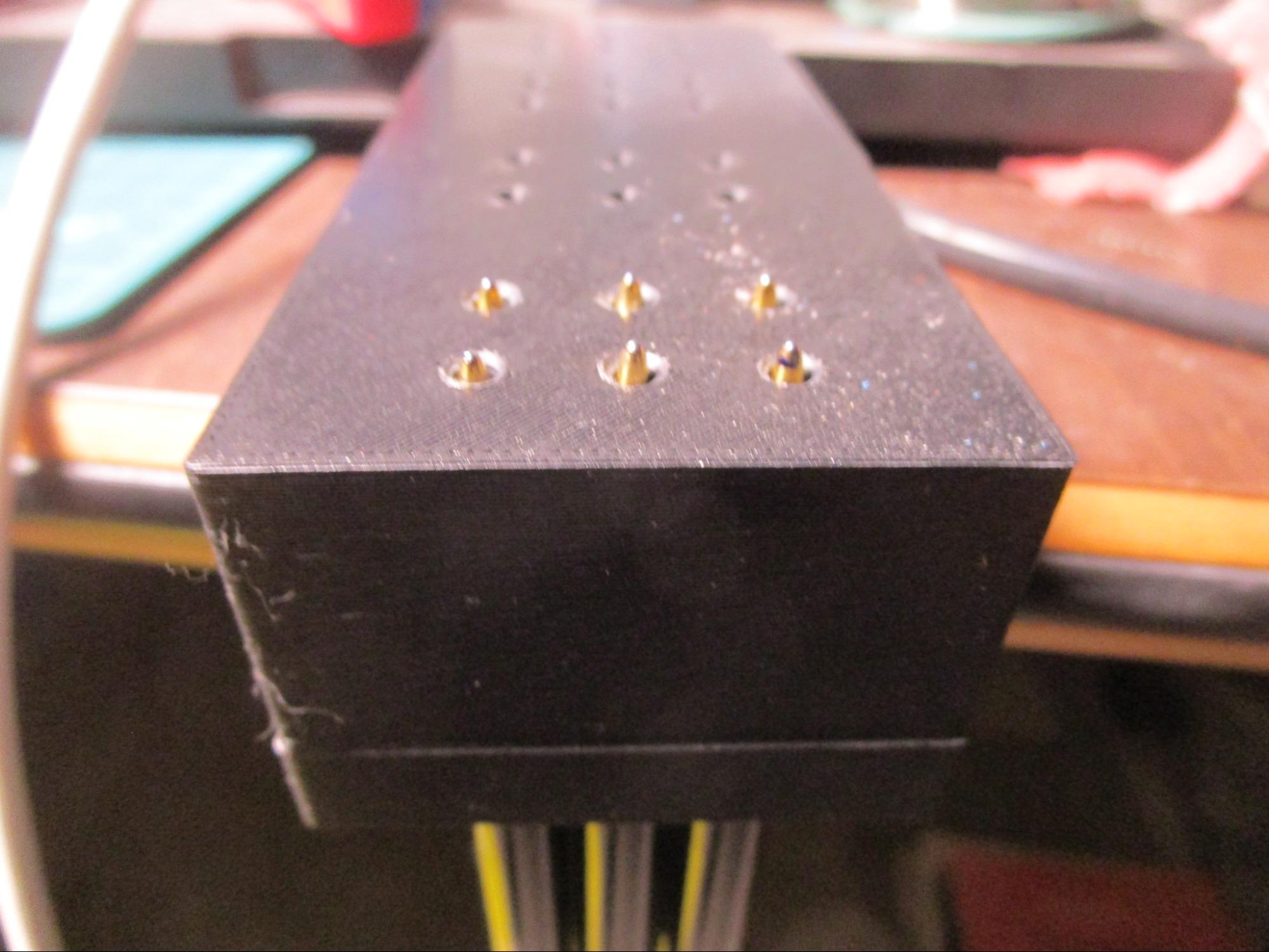
You then still need to have a dot, row or cell capable method of changing the state of the pins. Accuracy of the addressing method is a bit of an issue, at 2.5 mm pin spacing there isn't a whole lot of room but by making the 'target' as large as possible (say, 2.2 mm) and a 'pusher' pin that is less than half that size (say, 1 mm) you could get this to feasible if you can make the bi-stable pin mechanism in the first place. You'd also need to be able to sense the position of a pin (in or out) so that you can recover from power failure or any other state change that goes unrecorded. Here is an image of a test setup, scale 4:1 with 6 cheap retractable pens:
I think this would work. You could make a very cheap matrix display with it but it would be fairly slow to update and it would be quite noisy because of the bi-stable nature of the mechanism (which results in two clicks per set or reset). Miniaturaization would be tricky, especially the casing (which would have to be 2.5 mm at maximum diameter). You might be able to improve a little it on that by placing the actual pins offset from the center and moving the mechanisms out as far as the wall thickness to the next pin would allow within the body of the cell.
It would not live very long though, I can't find any reliable statistics on how long a pen retraction mechanism would last but regardless these are *much* (2.5x) smaller and would wear correspondingly faster. You could set up a bunch of cells and do an accelerated aging test to get a good idea of how reliable such a device would be.
For now I'm parking this one because it has a lot of already visible issues and has a very large number of parts (4 per pin, rider, case, spring). But maybe I'll revisit it for a matrix display.
Study #2, Odometer (Feb 23)
Cars from before the age of electronics had a mechanical odometer that is set up as a number of side-by-side wheels that each cound a decade. When a wheel reaches '0' it carries the next wheel to the left along to the next digit and so on. These are cheap to manufacture and have the advantage that you can drive the whole thing from a single motor, though updating the last wheel requires an exponentially higher number of moves for the first.
My initial thought was to make a number of cams that push spring loaded pins up or down. Each wheel would drive either 2 or 4 pins. But at a reasonable scale for actual use that concept would quickly fail: the cams would wear very rapidly and it would get awfully crowded in there with precision parts on par with what a typical watchmaker would put out. Much too expensive.
Then I realized that it might be possible to put the dots immediately on the wheels. that way you don't need any pushrods or slides or way to fixate the rods as long as the wheels can't be driven directly by the user, the downside is the wheel rotates in the direction of the reading so you need to work against that. But the greatly reduced parts count (no springs required and no physically separate pins) makes it more than worth trying this out. What's funny is that Mahmouds original 8 code wheel already had this but I was so focused on cams and 'proper' pins that I totally forgot this and I didn't like the diameter and shape of the wheel.
Here is a photo of a trial two dot wide wheel:
The dots protrude from the side of the wheel. To reduce the amount of rotation required to produce a pattern you can replicate the dots at different angles on the wheel, at least two offset by 180 degrees are possible (half the number of rotations required) and possibly even three. Another option to reduce the number of rotations is to allow the mechanism to spin in either direction, this would give you the option to move backwards if that gives a quicker path to the required combination.
Here is a model with three wheels in place:
Rotating a wheel through 4 different angles gives you zero dots, one on the left, one on the right or two dots. That way you need two blank spaces and two dots for all four combinations of two dots, which saves you half the rotation. For a six dot cell with one replica of the two dot pattern you'd have to spin the third wheel across three positions maximum (from 00 through 01, 11 and then 10) so that's three 'carry' operations, the previous wheel would then have to spin through three whole revolutions (so 18 carry operations) and the first wheel would go through nine.
With two patterns (00 11 00 11) a carry every half revolution the second wheel would have to spin 1.5 turns and the first through 4.5.
If you can put three patterns on a wheel (00 11 00 11 00 11) then the second wheel would spin once and the first woud spin twice. Two revolutions to pick any combination of 64 possibilities worst case, and on average only one revolution because on average you'd be only half the distance from the pattern that you want. That sounds very doable. Another interesting part here is that you could drive the first wheel through two small solenoids, one on the left and one on the right of the initial wheel mounted solidly to the axle.
This would protect against backdriving the wheels (modulo some slop in the gearing). It might also be possible to pick a suitable gear ratio to drive the wheels directly one to the other but it would be very hard not to have wheels 'in the middle' between two positions in order to position the furthest ones, similar to how when a clock indicates quarter past three the hour hand is already one quarter under way towards the '4' position.
Now the 2.5 mm inter dot spacing requirement actually helps us rather than that it hinders because it may help to allow us to squeeze in three patterns on a wheel. 360/3 is 120 per pattern, with each of the pattern elements (dot or space) offset by 30 degrees. That's nice because it squeezes the dots closer together making them protrude a bit further because they are both closer to the maximum protrusion due to the smaller angle (+- 15 degrees rather than +- 22.5 degrees). Here is a pattern wheel with three sets of patterns.
Placing this wheel is a bit harder than the one with two patterns because there is always something sticking out but it is still doable. It *might* even be possible to add another pattern but that would require a trick to place the wheels, they would have to travel through the sidewalls somehow. Maybe you could cut every other sidewall out completely so that the wheels can temporarily move into the adjacent slot while traveling upwards towards their installed position but that's a bit awkward.
You can clearly see that the two dots are spaced closer than on the first wheels with only one pattern, the inter-dot distance is 7 mm here, which corresponds with roughly 3:1 scale factor. The wheel itself however is still at 4:1 so that's not 100% fair. It might be worth trying to scale the wheel down to 3:1 rather than 4:1 to see if such an intermediary step is useful but I'd rather first finish the whole thing so that it conceptually works, then scale it down to say 2:1, make that work and then finally get it as close to the required size as possible while still keeping a functional unit.
Note that in a real design that whole wheel is only 7.5 mm across, so the definition of the patterns is going to be much harder to achieve than scaled up. A 2:1 version still worked quite well but a 1:1 version did not have enough resolution to be able to even resolve the dots with the eye, let alone by touch.
An interesting observation: when you move the patterns clockwise side-to-side they go through the following sequence (with the middle two positions being at the top of the wheel): 110000 011000 001100 000100. If you don't turn the wheel through a whole revolution and you use only one 'three patterns' segment of the wheel that means that you can replace the wheel with a simple lever with the two dots at the top rotating across only 90 degrees. The starting position would be '0', then the first is 30, the second 60 and the final one 90 degrees.
Either extreme would be automatically 'locking', one extreme because you could run the side into a block, the other because it is blank so you'd have the four zeros covered (the wheels won't spontaneously rise out of their slots) and one of the ones. That leaves three 'one' positions to be somehow locked. Another option would be to add two more positions to engage the carry to the next slot (but that would increase the covered angle to 150 degrees for an 'up' and a 'down' carry position), or you could drive each wheel individually (right away much more expensive).
Study #3, 3 dot wheels; orientation vertical (Feb 23)
Mahmoud's design has a lot going for it, it uses fewer drive train components but the ones he has used are fragile and expensive and I think there are some possible ways to substantially improve on the design. For starters, he uses 8 distinct faces, one for each of the possible 8 3-bit combinations. This requires a full 360 to position the wheel. It does allow for elegance at the edges where the pattern approaches the casing but that's a lesser problem in my opinion so it may be better to ignore that for now and focus on the thing that matters most: that the dots line up in *exactly* the expected place and that the drive train isn't going to be too complex. Because within a single character there is no room for positioning errors at all.
By laying the sequences out so that they overlap the number of positions on the wheel is reduced a lot: 000, 001, 010, 011, 100, 101, 110, 111 becomes 01110100 which when wrapped around the wheel allow you to select all of the combinations. But that has 45 degrees per position, which is not ideal because the middle position will be much more raised than the side ones. You can compress the pattern quite a bit, at 22.5 degrees per position you need 180 degrees for the full pattern and as with concept #2 you can use 15 degrees and then the whole thing fits in 120 degrees of the wheel, so you can put three full patterns on a wheel. The matching pattern is then at most 1/6th of a turn away from where you are right now.
Another option is to use the other 240 degrees for the drivetrain, either by turning the bottom of the wheel into a gear or, even more elegant by using the whole thing as a motor. This is interesting for several reasons: the motors themselves are obvious weak spots, they require some kind of downgearing and/or a feedback mechanism and they are probably going to be at right angles to the wheels to give them enough space to work.
Here is a sample with a 3 pattern wheel:
There is already quite a bit of room on the side so the wheel could be made thinner without penalty. There is quite a bit of gap between the dots, they are pretty easy to discern, the only part that is not so elegant is that the 'skirt' where the dots duck under the top surface is quite large relative to the size of the dots. The wheel is also about 2.7 times bigger in diameter than what would be ideal, at 27 mm versus the 10 that the specification requires. But the 'Orbit Slate 520' does much worse than that!
https://www.orbitresearch.com/product/orbit-slate-520-multi-line-refreshable-braille-display/
So that should not be a problem at all for now, better to have slightly oversized lines than no lines at all. The dot pitch works out to about 3.3 mm vertically, that's not ideal and it should be reduced by 30% to be standard conformant. There are two principal ways of doing this, the first would be to scale the whole thing down (part of that will have to happen anyway), another way is to further reduce the angle until we get to the right dot spacing. I think that's the most interesting option because it would further reduce the movement of the wheel during repositioning and it would maybe allow for a fourth pattern. Note that even a partial fourth pattern would be useful.
It is also time to reduce the wheel width a bit and to space any two adjacent wheels the right distance apart. And to make two characters side-by-side again instead of mis-using the old case.
Study #4; thinner wheels (Feb 23)
This one is a lot slimmer than the previous ones. It uses wheels that are not quite the right size (still too thick) but much closer to where we should be. It has three patterns per wheel, two wheels side-by-side per cell and two cells side by side for a two character setup. This brings the size of the dots and the inter-dot spacing much closer to conformance than before.
Having the three patterns on a wheel means we need to be able to move through 120-15 degrees for all 8 patterns to be exposed. I wonder if you'd only use a single pattern whether it would be possible to run the remaining 2/3rds of the wheel into a stepper with 8 positions. In hard drives such an arrangement is used to position the heads. A single magnet in the center could be used by the two wheels next to it (flattened in the middle) so that a coil riding the magnet would rotate the wheel. Hard drives use a servo mechanism and piezo electrics for the final detailed drive movement but we don't need that kind of precision, at 15 degrees per step all we need is a coarse positioning system with some kind of holding torque that doesn't break the bank in terms of BOM or assembly costs.
The feedback could be provided by a very basic quadrature encoder using leds on either side of the wheels or by deadheading it from a fixed reference point (for instance: a stop). An alternative would be to embed a magnet in half of the wheel and to put a bunch of coils next to it, each coil would pull the magnet towards it for that to become the indexed position. Travel from one coil to the next would dependent on the distance from the center of the wheel to where the coils live, this could be a multiple of the distance for the dots at the expensive of height and line spacing due to the increased swing of the arm.
A really steampunk version of this would use a spring and a pullrope, with the actual positioning mechanism somewhere else. To avoid calibration issues the return stop point would have to be reset upon power up (the point at which the wheel comes out of its rest position). The motors would live off to the side of the whole thing and take up as much space as you want. This is interesting, but fragile and hard to assemble and service but it would be pretty quick.
Another option is to use a travelling arrangement like in the Orbit 20 where a selector mechanism moves the wheel to the right position and then somehow locks it. I'm not a real fan of that arrangement, it has single points of failure and it's dead slow. For a larger display that simply wouldn't work unless you were really smart about the updates.
On the plus side if you did it for both axis it would probably be very cheap to build. The locking could possible be achieved by a ball loaded by a spring with a bunch of corresponding holes in the wheel, but from experience I know that assembling such devices is a complete nightmare. Another option might be that the presence of the setter carriage would automatically unlock the wheel, for instance by a relatively powerful magnet pulling back on the wheel lock. Moving the carriage would cause the lock to re-engage. That would also require a spring or there could be an embedded magnet to push the lock back into its position.
Study 5, Even thinner wheels (Feb 23)
These are the first dots that are as good as conformant.
The wheels are thin, only 2.6 mm (so off by 1/10th compared to what I was shooting for). Three patterns to a wheel like before. What's nice is that the pins are now so closely spaced they don't drop as much for the outer two pins. This makes it much easier to read the code.
Wheel diameter is about 27 mm. I didn't feel like making a casing for these thin wheels because it's pretty obvious that they will work, *if* you manage to drive them. Looking at the wheels side by side made me wonder if I couldn't use the pins themselves as the driving mechanism. That's possible in theory if it weren't for those large blank spots. This is a bigger problem than it may seem at first glance because any kind of drivetrain would have to engage with the wheels deeper than the pins if it is to work at all. But using a relatively 'sharp' (or deep, depending on how you want to look at it) wormgear you could probably do it. With one major serious problem which is that 2.5 mm over there is another such wheel which also wants to be driven, independently.
Which made me wonder how big a single wheel with all 64 combinations would be. The braille standard says that you can have a minimum dot spacing of 2.3 mm with 1.5 mm dots. 64 x 2.3 is 147 linear millimeters, which results in a wheel that is 46 mm diameter. That is *very* far from ideal. *But*, and this is a huge advantage, suddenly the drive problem is relatively easy to solve, you just index that one wheel to get a reference and then you rotate it into position, done. It is self locking (property of worm gears, as Mahmoud also noted) and it reduces the number of moving parts per cell to one plus a small motor. That's well into 'doable' territory at the expense of the line spacing. But as noted above in the bit about the Orbit 520 that's not entirely out of bounds though it would have been far nicer to be more compact.
At 46 mm / wheel an 80x10 line screen would be 61 cm wide and 46 high (no other buttons or controls taken into account). That's too big to take with you, but then again, 80 wide is the larger dimension. At 40x10 it would be in the large laptop domain. The 'deep' wormgear will be a pain but unless you want to use two motors at different angles it would be tricky to do much better. The wormgear would have to be only a little bit deeper than the dots, and the dots could be reduced in depth (they are probably a bit on the deep side right now) so hopefully not too bad. Another option, at the expense of some more wheel diameter might be to compress the patterns a bit and to have a 'dummy' part of the wheel that is all 'ones' so that we never have to drive the wheel on the bare part.
So that's worth a try.
Study 6; whole character wheels (Feb 24)
A single wheel, 46 mm diameter with all of the patterns on it in one go, 64 different index positions each of which expose a new combination at the top face. The wheel will use 1.5 mm dots on a 2.3 mm spacing (tightest spacing allowed under the standard), with 0.8 mm between the dots so that's 1.5*2 + 0.8 = 3.8 mm wide. Compared to the 7.6 mm that a cell can be wide this is fairly luxurious and it is possible that a drive from the side is also an option but for now let's pretend we're driving with the dots themselves. Reducing the size of the 'space' between two letters would allow for closer packing but that may not work for readers, I just don't know. Some kind of feedback will be required so that we know exactly what the position of the wheel is, or, alternatively we can drive the whole thing with a stepper.
But first let's make a wheel. I tried twice to make the 64 slot wheel by hand assembling the codes into a long sequence 64 positions long that contains all the codes but I kept running into problems and had to backtrack. After the second time I gave up on trying to do it by hand and I wrote a piece of code to do it. These are the side-by-side codes:
0011101000111011101001111011111001011010000010011001011010000010
0011111111110110110110100100011011001011011001010010000010010000
The top one encodes the left hand wheel, the bottom the right hand one. All combinations are present so this wheel can generate all 6 dot braille codes.
You could make index holes and positioning holes in the wheels to tell you where it is positioned. This could live on a thin circuit board positioned above the shaft. The front of the circuitboard could shine IR on an scale that is either embossed or it might be enough just to know when the index point is passing by. Another alternative would be to have 64 holes, one for each character position and one extra hole for the index. The lower part of the casing can house the rest of the drive hardware.
Crazy idea… So, now that we have the wheel with all of the 64 possible 6 bit character codes on them for 6-dot braille it still requires a motor per character, or some other drivetrain + locking mechanism. A simple drivetrain would require a gear on the side of the wheel, an idler gear and a wormgear. That's two sloppy interactions (resulting in wobbly characters) and complexity. That's also the expensive part and that's where everybody seems to run into the wall. They either economize and make carriages with bi-stable pins, solenoids, or they make it super expensive (or both…). But what if you didn't have to do that? Blind people read with their fingers and their fingers can't be everywhere at once. There are only so many spots where they could be and typically they will scan a line of text with their fingers. More experienced users may use multiple fingers next to each other and use the other hand to steady themselves when moving line-by-line. There is a great video here that shows the process: https://www.youtube.com/watch?v=pQLxJ2-zwVk
But what if we cheated? What if we only concentrated on those letters where fingers are, or even more extreme if we only concentrated on *one* letter at the time per line of text. This would allow you to move *all* of the letter positions using a single motor. As long as you're 'there' by the time the person has their finger on the spot and the character doesn't seem to move then that's fine. A single motor would be a bit rough though, because when scanning left-to-right for instance you'd want the next letter to be in place just before the reader reaches it but not too early or you'd be interfering with the previous one. So maybe two or even three motors per line (previous, current and next characters) would be sufficient to create the illusion of a line of text. Alternatively you might have a couple of motors per so many characters.
You'd need some way of figuring out where the users' fingers are and in which direction they are moving so that you'd have enough time to make the adjustment.
*If* - big if - this works it would create massive cost savings, you'd only need the one motor (or a couple of them) and an indexing mechanism per line of text. In an even more extreme example you'd be driving all of the lines at the same time as long as you only read one character at the time that'd be fine. It wouldn't be very wear friendly though. And the whole idea feels a bit like a meatgrinder so it would be quite important to ensure that you would never get your hair caught in there (which is a safety issue with any wheel based device).
Driving the wheels from underneath could happen batch wise as well by having multiple 'driveshafts' run from left to right under the wheels. Gears could be pulled into contact with the wheels and the driveshafts to rotate the wheels to the next desired position. Multiple wheels that need to spin in the same direction could be engaged at once and if a wheel is at the right spot it could disengage while the rest would continue. Once all wheels would be positioned correctly the drive motor(s) would stop moving.
If you have any slop at all in the drivetrain then the wheels can move a bit when the user reads the characters. This is more than a little bit annoying, the distance between the dots and the size of the dots is such that even a small upset can cause a character to be mis-read. The consequences (think online banking or something like that) can be pretty bad so mis-reading and mis-positioning should be treated as failure of the concept. In order to fixate the wheels they can be locked into place after movement (and unlocked prior to movement) in many different ways, but possibly one of the simplest and effective ways to do so is to simply compress a block of characters (ideally a whole line of characters). That causes the sides of the wheels to come into contact with a large amount of surface of the casing and this will cause a lot of friction stopping the wheels from moving by accident. One way to do this would be to have a servo that pulls down on a wedge that locks the main shaft under compression. Prior to repositioning you'd move the lock up again and then all the wheels on that shaft could be spun. If the wheels are all locked to the main shaft using splines then that isn't necessary. Another option is to use the shaft as a means of selecting which bank of gears will move. This will require some space (as much as you need for the movement) to the side of the character lines.
Yet another way to drive the wheels would be to have a magnetic clutch ride along with the wheel, the bulk of the clutch could live inside the wheel itself, the counterpart would spin along with the shaft. The clutch would not even have to be perfect, as long as some movement happens you can just keep it engaged until the wheel reaches position. This is difficult for another reason which is that you some how need to provide power to the wheel itself, but that may be solvable (though probably not all that cheap). Another potential issue is that a magnetic clutch requires a field that may well extend past the wheel that you're interested in causing torque on the adjacent wheels. If those are supposed to keep moving that isn't a problem but if they aren't then it may cause a wheel to move that should not be moving.
Another option would be for all of the wheels to try to start moving but only those that are unlocked would actually move. This would require a fairly precise locking/unlocking mechanism but that may well be a lot simpler than powering and selecting clutches. Each wheel could have an embedded metal disc and next to the wheel you could spin a fairly powerful disk magnet or a number of smaller ones embedded in a carrier. Having one central carrier per two wheels would reduce the number of magnets required and would ensure symmetrical forces on the magnet bearing drive wheel. Yet another option would be a friction drive on the main shaft that is easy to lock out again. This would require the wheels to spin quite freely (so we don't need a lot of friction to move them).
It may be possible to have an 'addressable lock' that consists of a stepper and a magnet on a belt. Where the magnet is the corresponding lock will engage or disengage dependent on the direction of the current, all of the wheels would be given the same lock or unlock command but only one would actually do it.
Two large wheels side-by-side in a casing, the casing isn't ideal yet and the skirt does not nicely line up with the tops of the dots. But this is 'draft' mode so very coarse layers and there is some play on the shaft. Fine tuning all that should make it a lot better. There are 5 rows of dots exposed in the window, that's two too many and shielding those from the reader is going to be tricky, the angular step between the dots is such that they are arriving nearly flat (good for the reading!) but that also means that the first two dots outside of the ones we are interested in are going to be *nearly* at the right height for reading. I'm not really sure how to deal with that yet, I can have some kind of cover over that part so your finger slides along the cover or maybe some other trick. One elegant way would be to have a depression that matches the shape of a finger at the spot where the centerline of the characters is, that way the 'high' parts would automatically cover slots -2 and +2 and slots -1, 0, and 1 would be neatly exposed.
If that works well then it might even allow for an even higher dot which would definitely be nice to have.
A wheel like this takes about 20 minutes to print in 'coarse' mode and an hour or more in fine mode. But if that makes workable parts that would already be a real victory. I think I should tune the dimensions and then move on to the drive train problem.
Study #7, Finger shaped depression in the casing (Feb 24)
The big wheels expose too many dots, this is a problem and it should be remedied. I don't see any way of solving this without bending the rules a bit. I'd like the top of the display to be perfectly flat but that simply doens't work with those large wheels, the initial drop at the top of the wheel arch is too low to reliably move the next and previous dots below the horizon. Very annoying. But with a very slight depression in the casing (alternative point of view: with a higher roof over the exposed parts that shouldn't be exposed) you can solve that problem.
The wheels are in between two 'proper' positions in this image and you can see that by the time they've rotated through to a registered spot that the dots in -2 and +2 positions relative to the center (the code you are interested in) will be under the overhang.
It's a difficult decision. On the one hand I'd like to make it 'perfect' but if 'perfect' means unaffordable then that is even more of a non-starter. I will have to ask a blind person whether they believe this trade-off is worth it.
I've done a lot of sketching and thinking about a way to drive the wheels reliably and without too much extra cost and I think it can be done with a single motor for the whole device (no matter how many lines it has). The basic idea is super simple: the main shaft is driven by a motor, shafts can be coupled on to the next or, alternatively you could have a motor per shaft ($, heavier). The shafts themselves would look like ordinary shafts but they really aren't. Inside the shafts at the 7.6 mm pitch (identical to the character pitch) there are embedded magnets. These line up with magnets embedded in the wheels. This then transfers a little bit of torque (up to the strength of the field coupling) from the one to the other. If it works really well you might even be able to replace the magnet in the wheel with a steel insert (which would be much cheaper). A steel ring with inward pointing teeth could work. But first I'll try the magnets. Either way, the really good news about this method is that this 'magnetic limited slip clutch' provides protection against stuff breaking if a wheel should get jammed and it transfers torque at the same time. There is still the problem of the wheel in frictive contact with the shaft, especially an issue if the wheel is stationary but the shaft is moving. That will need to be solved.
Another thing that needs to be solved is the locking of the wheel. For this purpose the wheels will need some kind of arrestor and a detection mechanism to work out when they are in the right position. I think this can be done with a relay like contraption that pulls a brake or a segment of a gear away from a toothed ring on the inside of the wheel. That way the wheel will only want to lock in place when it is exactly centered on a character and releasing the lock will provide that centering action even if the wheel is still a bit before or even past the position we're shooting for. A ring of locking gear teeth could be made in the wall of the wheel, then the unlock/lock action would be to retrieve a pin and to release it again. The pin head would be shaped like a triangle so that it would push the wheel into it's exact position.
In a perfect world the only points of contact with the moving parts are the end bearings of the shaft, and for every wheel the point where the arrestor makes conact with the wheel rim. But unfortunately the shaft is also a point of contact. You could make it larger to increase the wear area but that would also increase friction and reduce available space for electronics and the arrestor. Maybe a small ball bearing could be press-fit into the wheel. But small ball bearings arent't cheap.
Study #8, Hollow wheel, index holes, spokes (Feb 25)
This is starting to look like alien jewelry:
This didn't happen without some problems. The registration slits are super thin, only about .5 mm and as a result getting the first layer to be proper didn't work the first three tries. Finally after a very thorough cleaning of the printer bed I got a usable wheel out of it but clearly this isn't going to work for any kind of volume, besides that this wheel took a whopping 1h 20m to print. Not ideal, to put it mildly.
In this picture you can see the light shining through the registration slits so it did eventually work:
But I would like a more reliable design that isn't as finicky to print.
While this was printing I was playing around with some options for locking the wheel and the first two (re-use of the slits and half circles cut out in the inner part of the rim) didn't really look good and didn't give me a feeling that they would be reliable.
So I re-did the whole thing, removed the spoke holes and added a ring of teeth to the bottom of the wheel.
That looks more reliable, the idea is that a spring loaded pin with a triangular (or just pointy!) head aims for the valley between two of the teeth. That should then lock the wheel in place and guide it.
Thinking about this a bit more: *if* that guidance works across 1/3rd of a tooth then that implies that you can use three of those 'lockers' to move the wheel around stepwise. That would require two of them to be powered up at all time (two *per wheel*) and that's a bit power hungry, but once locked in place it might be possible to release the other two without the wheel moving away from its set position. Two 'unlocks' would create a move. The 'dominant one' (the one that actually lines up with a slot) could be given a stronger spring so that the other two can be relaxed without being able to overpower the one that matters. Or maybe they'd cancel out (because they are both resting on opposite sides of a tooth).
This is quite interesting: it allows for stepwise movement of the wheel in a completely mechanical and automatically locking manner, kind of a mechanical three phase drive. I'm a bit afraid that it would be noisy, but that's mostly a matter of the material of the locking pins and whether they click against something in the back. In the Yamaha disklavier piano's there are massive solenoids that have been dampened to the point that you don't hear them at all. But there they have a lot of space to work with.
If that works we no longer need a motor, the two magnets per wheel can be dropped and the wheel boss can be made the full 7.6 mm, so it will carry the wheel much better. We no longer need the slits other than a single 'home' slit to make sure we can sync up after the unit has lost power. The shaft that everything is mounted on would then be completely passive.
Another option would be to create a 'pancake' stepper motor with four small permanent magnets as the rotor and eight coils as the stator windings. That's pretty tricky though, even at only 64 steps per revolution that would require a lot of very precise engineering. It *might* be possible to use only four coils and a completely passive rotor (no magnets, just some steel teeth). To lock that you'd need some power though.
I'm a bit worried that if the lock/unlock mechanism would be used to drive the wheel that it might result in either a lot of noise or premature wear of the springs. We *could* use magnets instead of springs but that has it's own set of problems (it is also quite costly).
And I'm not even sure if it will work. If it does though, it might be worth it to try an accelerated aging test to see how long that setup lives.
These are about 10mm on the side:
So maybe that 'stepper' motor isn't such a bad idea. Another option would be to use only three coils, and to have the three coils offset by 1/3rd of a tooth. I really like the idea of making the wheels the centerpiece of everything, so they can be the code carriers, the indexer, the lock and eventually possibly even the motors. But a standard motor as the main component for the drive train also has its advantages, it ensures that that bit will be solid and reliable and more or less standard. It also keeps the wheels simple and robust and it wouldn't need a custom piece of metal to ride inside the wheel. Though such components may well be unavoidable. I would really have liked to have everything except for the wheels the wheel casing and the circuit board to be 'off the shelf' but that may simply not be a possibility with this project.
If you want to drive the wheel as a stepper rotor then the coils would have to be centered over the teeth. There would be 4 times 16 poles, so each coil engagement would immediately move the rotor to a new letter position. The advantage of doing that is that motor + lock are one and the same, you just keep the coil running at a lower current to fix the wheel in position.
Another advantage is that we can use standard double-H bridges to power the motor and likely (because it doesn't have any opposing force) it wouldn't take all that much power unless you *really* tried to stop it. But in that case it's fine if you succeed with that rather than that it shreds your fingers (because all of those dots at high speeds of rotation are probably an excellent way to get hurt, it already feels like very coarse sandpaper).
4 coils + 16 magnets spaced around the wheel would give you that, but 16 magnets is quite expensive (they're typically $.20 or so each). More coils = fewer magnets, but coils are also not cheap. But coils can magnetize more than one part of the device, you can add a little piece of metal and bend it up in a different place to move the magnetic field around. Before long you'll be making an actual stepper :)
But steppers make a lot of torque and we don't actually need that so maybe we can get away with much higher resistance coils and thin metal or even without any magnets at all, just metal inserts into the wheel at 16 spots. That's worth trying.
A simple metal insert would be a small nut pressed into a cavity in the wheel. The coils would have to ride pretty close to the metal to be able to attract it but I don't see any reason why that could not work.
A test with a single magnet in one slot and a small not in the oppositng one would give an idea of whether or not this can work or not.
Not exactly high grade CAD work, but at least it shows the idea. So the four coils have a common wire and one that goes to the drive unit. Depending on whether you want 'full step' or 'half step' you'll need either 16 or 8 magnets and for 'half step' the stator pieces would have to be twice as far apart. Probably half step will require a bit more power because the coils are going to be much further away from the magnet. But it will cost much less per wheel. If the system already works with just a captive nut to attract then it is probably better to go with full step.
So, all that work to put those blocker teeth in there look to have been for nothing I find this idea too intriguing and I would like to try it. If it works it might just be the solution to all of the remaining engineering problems, it would also make the whole thing come in at an affordable price point.
Study #9, stepper integrated in the wheel (Feb 25)
There are two major variations on this theme: coils inside the wheel (more compact, less assembly friendly) or coils outside of the wheel (far less compact, but *much* easier to put together). For now I'm going with the coils outside of the wheel option. that will make it much easier to test things and if at some point I can get this to work and it looks reliable enough (and so that the neighboring wheels don't interfere, which is still a bit of a worry) then I can see if I can move the coils to the inside of the wheel (all that wasted space…).
So, for the first time we're going to have some electricity involved. The redesigned wheel looks like this:
and yes, it is horribly ugly but right now I don't care about anything else but the drive and the lock because that seems to be pretty much the only hard problem that is left. One hard problem will be to ensure that with so many coils drawing power in the machine that we don't end up either overdrawing the power supply or emptying it too quickly (very important if the device ends up being battery powered).
This isn't a trivial problem to solve, but there are some hints about what might help: the current required to move the wheel to a new position could be substantial, but once it is there holding it there should be far less power draw. The power draw will probably be directly proportional to the amount of space between the coil core and the insert (magnet or piece of iron). And finally, you only need to 'hold' those wheels that are being read and maybe there is a way to detect the presence of a finger (capacitive, for instance) which would then allow you to ramp up the holding torque briefly. The wheels shouldn't all move at the same time, that will draw too much power but you can set an upper limit and then only pass the remaining information down the line when everybody 'upstream' is quiet. You could update multiple lines at once.
I think i2c is a nice and simple bus to use to string the devices together, alternatively something like what the WS2812B LEDs use might be applicable (though it runs at clockrates far in excess of what we need here). Either way, the idea is to daisy chain the wheels one to the next so that the microcontroller has a very easy time of interfacing with a display (essentially just one or two io bits).
The stepper test will use four coils, and 16 inserts for a full step test and four coils 8 inserts for a half step test. I'm fairly sure that 'quarter steps' will not work (the distance from the coil to the thing that it attracts is just too large) and I'd already be very happy if half stepping works (and works reliably enough that the wheels position accurately).
I'll need to finesse some coils for the test, maybe I can strip some print relais down and re-use the coils from those. Ideally the coils would end up mounted on the circuit board inside the wheels but for now I'll just make a test rig with a single wheel to see if it will spin at all.
If this stepper trick works I won't be using the encoder ring other than a single index pulse. But it might be somewhat useful: you could use the encoder ring to detect that a wheel is blocked because you didn't see the corresponding edges from the detector. Oh, I just realized you only need 32 holes for the encoder, you can use the rising *and* the falling edge separately. Just line up the edge with the slot. That would at least make the encoder holes a bit more manageable. And 'maximum light' (center hole) and 'minimum light' (center block) are also useful signals so maybe even 16 holes would still work though then the holes would get quite large and you are probably going to lose accuracy. But it might be enough to detect a stuck wheel, especially if you can store the minima and maxima of an unobstructed run for comparison.
Here is the wheel loaded up with little (6x2mm) neo's. I tried rotating the wheel with just some M3 nuts in there but it wouldn't work at all, basically you have to be within two mm or so before it would have any effect (5V coil from a small relay).
But with the neo's in there it worked reasonably well (that is, it attracted over a large enough distance that I think that I will be able to get the wheel to spin).. The big issue with this arrangement is that the next wheel over (and so on) will have another 8 neos in it. Once those all line up they will want to be close to each other far more than either of them wants to align with any electromagnets that happen to be close. So it does not immediately look as if this is going to work. A normal motor has a lot of metal short circuiting the magnets and here we do not have that so those stray fields are quite a problem. One possible solution would be to have a steel insert with some fingers focusing the magnetic field outward. Then you can load that up with magnets the strength is enough to interact with the coil but not so much that it affects the neighboring wheels. (and quite probably even the wheels in neighboring lines as well!!).
These little neos are ridiculously strong, the coil could *barely* pick up an M3 nut but the neos (which are 1/20th or so of the volume of the coil) will happily pick up a pair of pliers!!
Shielding with either mu-metal or plain steel between wheels is of course also an option but more cost and complexity, and it will use up some of that precious space.
Another thing that might work is to drive one wheel from the inside and the next one from the outside alternating the position of the neo's. This may work but it would be very easy to have a positioning error on the wheel that is driven from the inside because of the angular errors multiplying across the much longer difference in radius between where the magnets are placed and where the read-out takes place.
Another option, not quite as nice but it would work: little motors with a tiny pulley driving a much larger pulley integrated into the side of the wheel. The encoder would take care of the positioning and the motor would start up if the user would try to move the wheel outside of where it is supposed to be. You'd need two sets of LEDs and photo diodes for quadrature encoding and then you could even spin the rotor backwards and forwards at will. Not bad in itself, but a motor per character really adds up weight wise (of course, so does every other drive train). The advantage of that would be that it would be using no power unless a wheel was moving (or being forced to move). Another disadvantage is noise, those motors would have to be isolated really well.
Little motors might not live for very long though. Usually they are 'toy grade' and anything more serious would right away cost a lot. What's little? Well, check these out: 3 mm for the small one and 6 mm for the larger ones!
These are from a toy helicopter (remote controlled, no less) which sell for 35 bucks including a remote controller. So those motors can't be more than pennies but building them deep into the device would mean that if the motor fails you have a complicated service to perform. making the character cells 'pluggable' would remove that problem.
Study #10, Stepper test, (Feb 25)
Running the wheel as a stepper isn't all that simple, you need four coils very precisely positioned around the wheel and you need a bunch of electronics to drive them in sequence otherwise the wheel won't turn. It's a pretty crappy stepper in that it really only has four spots where it drives the wheel rather than in many places but we don't need to develop much torque, just enough to overcome the friction on the shaft.
Here is a sketch of a simple test stand, a base with four dismantled relays positioned strategically around the wheel (only one relay in the picture, the other three are the squares on the paper). Each relay is offset just so that it can attract the next magnet in sequence. Between two full steps the 'half steps' double the number of positions we can select. This is a bit tricky and highly dependent on the consistency of the positioning of the coils, the number of windings, the current stability and the strength of the magnets. But since it saves half the magnets I think it is worth trying to see if that gives satisfactory results.
The wheel could be made the full width of the slot minus just enough room to smuggle out the coil wires, and a metal base to hold the whole thing to shield the neighboring wheels. That way adjacent magnets would not interfere with each other. Having the wheels that wide would help too with embedding the magnets, using really small ones (say, 2 mm) and fewer ones would also help to reduce the chances of the magnets interfering with each other.
Coils would lay flat on top of one another with the pole pieces protruding from between the coils. Those pole pieces would have to be very thin to allow for room to be left over for the coils themselves! You'd have to make them from thin sheet steel (lamination steel, very good magnetic properties). They'd be 0.4 mm each so with a wall of 1 mm on the wheel and 1 mm between cells that leaves 5.6 mm for two coils and four stacked laminations, which isn't a whole lot. Maybe the outer wall could serve as one of the pole pieces but then it would lose some of its shielding properties.
Another possibility is to have one coil on the inside and one on the outside, the one on the outside would live in the bottom half the case and the other would use the whole circle on the inside. The inside one would have a shorter arm so probably less accuracy and less holding/moving torque.
Josef Prusa should get a statue, a bit more than an hour to make the test stand:
Some more relay mutilation
A lot of fiddling later I have it working!!
Initial tests: a bit noisy, probably due to inaccuracies in the machinery but when it is running slowly you can't really hear it. This should be easily fixable using more accuracy (for instance less axle play). The prints for both the wheel and the test stand itself were 'draft' mode so 0.3 mm layers, That alone probably accounts for a lot of the noise and there is some play in the shaft.
There is almost no torque. I don't want the system to have too much torque anyway but this is just way too little. The speed is pretty impressive, in full step mode it will go down to about 60 steps per second, and in half step mode to a very impressive 200 steps per second. That's 3.5 revolutions / second, and because you're always within half a revolution of the character you want that's 1/7th of a second update time!
So what we have now is a four pole, 8 magnet 32 step per revolution operating in 'half step' mode. Accuracy isn't very high yet, I can clearly see that some steps are not quite moving enough and others a bit too much. This is likely due to various inaccuracies as well as the fact that half-stepping isn't the most accurate thing that you can do with a stepper. Using 16 magnets would solve that (4*16 = 64), but it would cost quite a bit more and I'd like to reduce the parts count and cost rather than to increase it.
Hard to believe this worked on the first try even with the crappy setup, the low supply voltage and the less-than-ideal mechanics.
Next step will be to tighten up the mechanics a bit, all that slop really doesn't help and I'll add a bearing to make it more quiet. That should also improve precision. I'll reduce the air-gap between the magnets and the coils a bit which should improve the torque and probably the overshoot (which is quite noticable when stepping slowly). Adding a bearing was easy, I found a computer fan that had two really cute 8 mm bearings in it so I took it apart and used those. The inner dia is 3 mm so I've just snapped off the old 'shaft' (for want of a better name), drilled a 3 mm hole and stuck a drill in there. That's good enough for now and immediately it is a lot more quiet and it also spins much faster. Interestingly, there is now so little friction in the system that any dampening effects are gone and you really start to see how the magnetic fields act like a spring or an elastic band.
I can now see three full paths to the finish line: the current mechanism with either the steppers moved 'inboard' or outboard in the corners of the device (or in an extreme case: both, for maximum torque, though that would be more expensive than strictly necessary). Another option is to use a servo mechanism with an encoder and a regular little DC motor. This would require a drive component (gear or belt) as well (finicky and not a good life span). And finally a stepper motor such as is used in CD drives to engage with gear theeth on the side of the boss on the wheel. This would be pretty tight, those have worm gears that are three millimeters wide. The one big advantage of that method would be a very high holding torque even when not powered, but it would wear like crazy and likely not live long, especially not if a wheel should ever get jammed, the motor would just shear off the pins.
And you'd be dependent on sourcing those things and if there is no longer any economy of scale (for instance: because CD drives are very much out of fashion which really is already happening) then you would no longer able to make the device.
I'm a bit worried about the accuracy in half step mode. I could switch to 8 coils with 8 magnets or take the easy way out with 4 coils and 16 magnets, so I'll do that instead. That way I'm 100% sure that the angular movement is accurate and any registration error is eliminated. it's a bit crowded around the circumference if the wheel with these large magnets (hah, when I first started working with them I though they were small…), but presumably we can improve on that by using smaller diameter magnets or by using a single disk magnet with a bunch of fingers under it. You could alternate positive and negative poles like that as well which might open up some other possibilities.
What I really like about driving the thing on the outside of the wheel is that you have the full width to work with and if you use smaller magnets in the core of the wheel you minimize the chance of interference with the neighboring wheels because the distance between the magnets is a bit larger.
Another issue I've noticed is that the wheel wobbles a bit at the perimeter. This isn't extremely obvious but it might cause friction, wear and tracking errors near the top with the dots moving side-to-side. A full thickness wheel would eliminate that because it would ride against both sides of the case, but ideally I'd want the wheel to be free of the sides of the case by a tiny margin to cut down on wear.
Next step: a 16 magnet wheel and a 5.625 degree offset set of coils.
Study #11, 5.625° steps, 16 magnet rotor (Feb 25)
This necessitates a new test stand because the coils need to be re-positioned. I had to make a new one anyway to better place the 3 mm shaft at the center (I eyeballed the second test with the old one, it worked but it probably was a bit off-center).
Another issue is that the wall thickness is getting a bit low and the force required to push the magnets in is rather high. Between the two of them the wheel cracked in one spot. And the center boss that the bearing presses into is too thin so that will need to be fattened up a bit and maybe made higher to further reduce the wobble. It might be possible to make a 'fat' wheel in which case there could be a second bearing on the other wall.
Not the most productive day so far :( One of the sticking points is that with the wheel expanded to 16 magnets that there are a lot of opportunities for a magnet to meet something that it really likes. And once that happens you need more torque than the coils can (currently) provide to unstick it. This is a problem because with 4 poles and 16 magnets there is simply no way the coils are able to make the rotor move except for when they are 'lucky' and there is no nice match between an unpowered coil core and a magnet. As soon as that happens it is game over, and on average that seems to happen every 4 steps.
This is the second, higher version of the rotor with the thicker wall):
I see absolutely nothing wrong with it, but I can't get it to move.
This needs to be solved before there will be progress again. One way to solve it would be to double the number of motor poles, but that's difficult because of the way the coils are set up. Essentially by the time you do a full 360 you've lost one pole that you will not be able to make up.
One solution that I've thought of would be to give more (rather than fewer) magnets something to lock on to, that whey they will cancel out and the rotor should spin more freely without locking. The trick will be to balance the forces in such a way that it all adds up to 0. I'm going to try to achieve this using little nuts embedded in between the coil slots and one more at the last station. That way it does't take up more space on the test stand (that was empty space anyway).
Quite a few hours later… still no progress. This is frustrating. I don't quite understand what is going on. There is almost zero torque and the wheel twitches a bit but doesn't move to a new position. I'm going to make yet another wheel with the magnets radially to see if that narrows the field radiated by the wheel enough that it stops locking up. But it also doesn't really lock up, it spins quite freely if you give it a shove, it is when it is moving slowly that it starts to behave quite odd. Why 8 magnets worked flawlessly and 16 magnets doesn't work at all I don't quite get. You'd say that the only difference would be that the 16 magnet version would move with more accuracy but apparently things are not so simple.
I must be missing something very obvious here but it isn't cooking.
Study #12, radial magnets (feb 26)
This also doesn't seem to solve the problem, though it does seem to cog much less than before.
Interesting finding: at very low voltage and with slow pulse trains without any passive bits of metal it *does* actually move. Apparently the friction is so low now that the overshoot is tremendous and if you use a lot of power and then move too fast to the next pulse then you overshoot!
Ok, found it. That was *very* annoying. The ground of one of the coils had become disconnected inside its sleeve! Absolutely invisible. But now it is working as expected. I noticed because the current consumption didn't match what I expected during one phase engaged.
A lock might still be useful. But it need not work on a per-character basis, it is probably fine to lock a whole line at once, and to unlock the line briefly if a character on the line changes. If cells are to be 'modular' this will require some trickery with fixing the cell in place, ideally you could exchange them without any tooling and a lock from below that works on all of the cells at once would probably interfere with that goal.
Another thing I'm still concerned about is to what degree a cell is going to have an effect on the cell next to it. And if cells can be individually locked/unlocked you could protect against that to some degree, for instance by unlocking all the odd cells first, updating them and then locking them, then do the same for the even cells. The metal bits weren't useful so I'm going to remove them again, so we're back to using the test stand V2 and both wheels (with radial and axial magnets) work. The radial one works slightly better, it starts up at a lower voltage too and it stabilizes sooner.
Here it is running at speed:
I'm not usually happy about motion blur but this time I am :)
This is the rotor when it isn't moving:
It's dead quiet by the [e]way, you can't hear it at all even with your ears practically glued to the device. This looks very promising. I'm still using half stepping but the wheel does not come to a stop on any of the odd numbered positions so there is always a character exposed.
The 16 magnet wheel is fairly heavy so it will build up a lot of momentum as it moves, especially when going faster.. This manifests as overshoot when you try to stop it. A ramp-up-coast-ramp-down approach might eliminate some of that.
So, now that this works: what to do about those coils? These are pretty big and ugly to boot, it would be nice to replace them with something that is *much* easier to integrate into the device and preferably not scavenged from relays.
I see two possibilities: the first is to stuff the coils into the four 'unused' corners of the square enclosing the wheel. That should in theory be plenty of space, but the angular offset may cause some issues there. Also, 16 magnets at $0.20 each is a big chunk of money, and a lot of work to assemble. It would be nice to replace them with a single magnet that is much larger and a metal spider for the stator. That will also be easier to assemble and in theory would allow for a 256 per rotation stepper, so four positions between each of the steps. The coil offsets would then be much smaller than they are now (5.625 / 4).
Another option is to place the coils inside the wheel. That's easier said than done but there are a lot of advantages to doing so: it allows the coils to use spiders so they'd work on the whole circle at once (probably much better torque) and the outer portion of the wheel would still be available for electronics. It would make things a little harder in terms of cooling. Yet another option with the coils on the outside would be to use a 'short circuit' rotor that contains metal that feeds the magnetic field to an opposing coil. That way there would be no permanent magnets at all, which would save a lot of money.
The number of options is increasing and that's nice but it also increases the chances of following dead ends. I like the radial setup, it probably will work best when using coils outside of the wheel but if the coils move to the inside of the wheel then the radial setup uses a lot of space in the wheel and that space can not be used for coils.
Coils inside are also nice in that it may be possible to use only a fraction of the number of magnets that we are using right now, one on one side of the stator and one on the other.
This seems like the best solution, but making four stacked coils that small is going to be very hard, essentially there is only 5 mm or so (wall, circuiit board, coils, spiders(4!), wheel, next wall) for that whole stack and that isn't a lot. This also increases the risk of interference with the next wheel because the coils at the extremes are very close to their counterparts in the next character cell. Applying 'holding current' to the wheels next door is probably going to be a requirement. Each set of coils would be offset half a tooth from the other. Some passive shielding metal could also be made part of the wheel but an airgap might work better and maybe the field will be contained enough by the spiders.
You could also make the four coils as quarters of the space inside the wheel (but then you'd need all 16 magnets again).
It might be possible to do away with the walls in that arrangement as well. You could just have a stack of wheels spinning side-by-side with a tiny gap between them. That would allow for maximum space for the coils but wiring them would become a nightmare (you'd have five wires come out of each character slot that need to make it to the controller somehow).
Yet another option is to put two coils on the inside and two on the outside. This would require some careful balancing of the forces so that you don't end up wiht a lot of torque on the one set and very little on the other. It would also be bad in that the outer coils appear to work best with the radial arrangement but the inner ones need that space so they more or less dictate the use of the axial shape.
Yet more possibilities: drive the coils with an H-bridge rather than to have four independent coils and reverse polarity to get the effect of four coils while using only two?
Torque (holding torque or moving torque) could be increased by running the coils that are not attracing the magnets in reverse. That would cause the magnets to want to avoid that space. This should be relatively easy to test: reverse the coils and drive three of them on and one off.
Ok, so that actually works. I just reversed the state of the output bits after reversing coil polarity and it does exactly what it should do. That trick will work with any magnet/coil arrangement, it's mostly a matter of drive electronics, ideally you'd use an H-bridge per coil (so 4 H-bridges of 4 transistors each) so that you can reverse the polarity of the coils. Then you'd drive 3 to exclude and one to attract the magnet for max torque.
Funny thought: you could do 'blinking text' by rocking the wheels up and down a fraction of a character. This may seem like a useless gimick but you can use it for cursors and such, and you could even use it to make a gray scale like effect if you withdraw the wheel a bit into the casing ('fading out the text'). Gray scale is a bit rude in the context of blindness but the effect would be analogous, the text would sink into the page in the most literal sense possible.
Yet another option do drive the motors. One problem with the way things are arranged right now is that the field has to travel through the face of the wheels. This makes things awkward: the faces have the studs on them which increases the air gap and the magnets have to ride a bit back from the face to allow for some material to remain. A possible improvement would be to lay all of the magnets flat in the wheel in cavities you'd then drive the wheel from below (if you think of the wheel as flat instead of upright the way it is going to be mounted in the case).
That's interesting for many reasons: the airgap can now be reduced to an absolute minimum, you could probably use *far* smaller magnets which would reduce the weight of the wheel considerably and it might be possible to put the coils directly on the circuit board as part of the traces instead of as a separate component. This would also greatly enhance the placement of the coils and would allow you to drive *all* of the magnets rather than just the four that happen to be in front of the coils. That's worth a try I think, but circuit boards and such will have to wait until we are approaching something like a final design so better to make another test stand and another wheel.
I also tried a quick alternative version with inserts in between the coils to improve on the fact that the magnets keep seeing a different amount of metal (which is the root cause of cogging) but that didn't help. (teststand #11/2)
Study #12, magnets flat, drive from the side (Feb 26)
This wheel is a bit more tricky than the ones so far. There is only a very thin layer of material for the base of the wheel and now the forces acting on the wheel will work directly against that thin layer rather than across the wheel towards the drive shaft. Any kind of play in the bearings or flex in the material will immediately have an effect on the wheel itself as well as on the positioning of the wheel in the readout window. Smaller magnets would certainly help but I only have the 6 mm x 2 mm round ones right now to play around with so I'll have to live with that. Another issue is that now the magnet fields and the drive fields are aligned across the long axis of the device rather than into the space around it. This massively increases the potential for one character to affect its neighbors.
You can combat that in a number of ways: apply holding torque to the neighbors that aren't supposed to move. Synchronize movement between neighbors as much as possible (this creates some very non-local control problems which would massively complicate the software). Shield neighboring characters from each other magnetically. For instance if you made the wheels of steel with a plastic rim with the dots on them that would be one way to create a shield that doesn't require extra space. That would add a weight penalty though, and accelerating and decelerating more mass means that the machine uses more power.
Driving this wheel, even temporarily is harder than driving the previous versions, those could be driven from the space around them (which is plentiful in these test setups). But this wheel with the magnets oriented flat is a lot harder to drive, the drive magnets will have to move under the wheel somehow. But since that is how they will eventually be deployed we may as well embrace it. I'm envisioning some kind of enclosure that you slide the coils into. This will be a lot more compact than before so I'll have to make sure that there is enough room.
Another lock option: to short circuit the coils that are not in the path of alignment so that any magnet that wants to move into that slot will be repelled by its own mirror image field.
The wheel is done:
The drive side is the other side, the magnets are almost (.5 mm) on the surface so that's going to be a tiny air gap. This is even more suitable for a thin spider riding side the wheel with a few of these magnets to get a field.
And now that I have this wheel and I've thought about a way to drive it I suddenly see that there may be a way to get that original idea with the three bits on top of each other or two bits side-by side to work. But that can wait for now but it is a nice option to have just in case this becomes a dead end, or if we can make that one work better.
I can see some inherent advantages to this bigger wheel, for instance it always lines up the two columns, it levels the wear across a much larger number of dots so that should help longevity, it's super simple to assemble (just pop the wheel + circuit board into a case) and it is locked in one direction of movement by the design itself, you only need to stop the wheel from rotating.
But the smaller one is *smaller* and that's a huge advantage, it would probably be cheaper to make, would use less power, can't lose synchronization and update faster. Besides, the smaller ones doesn't even need a whole wheel, all it would take is 1/3rd of a wheel at 24 mm radius or so. With that 8 mm bearing that means that only 16 mm would be required for the 'wheel'. The left and right side of that cell would be driven at different distances from the center so they don't interfere. A casing that size is a lot smaller than the one for the big wheel (but there would also be less stuff in the casing), and that's a serious challenge.
Here is a sketch of what that could look like both halves would be partially concentric:
I'm pretty sure you could make that work and I will re-visit this once I have all of the challenges of the bigger wheel figured out. There are probably many more lessons left to learn from that. Next up, the testbed to drive this wheel.
Hm, yet another idea about that partial wheel version: it could even be voice coil activated, where you would calibrate the amount of current required for a given deflection.
Study #13, test driving the flat magnet wheel (Feb 27)
The testbed took a while to make, it wasn't obvious from the beginning how to lay it all out, I ended up tweaking the other testbed until I had a good enough version to play with, here it is:
The coils live in the four spaces, the wheel rests on top of the shaft like before. But the magnets are now pointing 'up' (which in a real device would be from the right hand side of the wheel). I'm running out of PLA (the 3D printer has been running pretty much non-stop for the last week) so I've put a bunch on order. Silly details but it could easily cost a day or two if I had not noticed. I couldn't bring the magnets in close enough like this, so I made another one to open up the centers and to move the magnets in further towards the center, this also required trimming the base of the coils so the coils wouldn't interfere with each other.
And here is the wheel to go with it:
Note the super thin layer at the bottom that retains the magnets. This could be reduced to zero if you really wanted but then you have to glue the magnets in place which I won't do for now.
But… it didn't work. The problem is that the magnets are so strong that they will overpower the magnetic field generated by the coils by a considerable margin. The effect is that the magnets will lock on on the cores of the relay coils and that will be that. The 'weak' version was better in that sense, the distance between the cores and the magnets was so large that the coils made a difference. But once the airgap is down to nothing it is game over. This cogging effect is a major showstopper, but I have an idea on how to improve on it.
It's interesting though, I learned a ton about how the magnetic fields in a motor or generator balance. I made a windmil a decade and a half ago and all that knowledge comes in very handy right now, but there is a major difference between getting a power generating device not to cog and doing the same thing with a stepper motor whose position is expressed in thousandths of a degree. That is a wholy different kind of demand.
What I've also decided is that for now I'm willing to compromise on:
I do not care if it takes a nuclear power station to run it as long as it works and I don't care how much a single item will cost. Things I'm definitely not willing to compromise on
Study #14, very flat coreless coils (Feb 27)
So, what if you didn't need those cores? Just have cores that are all copper without any metal inserts to focus the magnetic field. This would require a ridiculously small airgap to work, but since we have no space to begin with I see that as an advantage and it might also help against wheels interfering with each other. The 'runaway fieldlines' are still quite focused when you are close to the coil, they start to spread sideways in the airgap and the whole point of the metal core of an electromagnet is that you focus those lines to where you want them: the exact center of the coil. But metal also introduces complications, for instance you might end up permanently magnetizing the core (so you'd need to de-Gauss the core!).
First step is to make a bunch of electro magnets, I scrounged up an old solenoid from an electric piano, and made a coil body and wound it. That seemed to work. Then I printed a bunch of absolutely tiny cores. These are 20 mm across but only 5 mm high, the lower right ones are the lids the rest are the core bodies. They're obviously not very strong at that thickness so removing them from the printer bed was a bit of a chore but it worked.
This is what they look like assembled (USB connector for scale):
And here is the assembled coil on test stand #6.
I wished I could say that that did the trick, but alas. As you can see on the lower picture the winding of the coil (on a cordless drill) pushed out the retaining flange so it rides a lot higher than it should have and that means that the airgap is much larger than it was meant to be.
For a quick test I put in a 2 mm drill to serve as temporary core but that of course immediately cogged like mad, enough to pull the wheel over! So this isn't going to work as is.
I did get to practice my coil winding skills and now I'll go and make another testbed that will hopefully eliminate the cogging issue.
Study #15, More Metal (Feb 27)
If coreless isn't going to work (and there are many reasons why it seems that that isn't going to work unless everything is 100% flat and there is absolutely zero play in the bearings, which is not exactly the case with the ones that I have) the we could alternatively fill up as much of the unused space with metal to make sure that the magnets always see an equal amount of it. The only differentating factor left then is the magnetic field of the coils as if the metal isn't there at all and that's the best way to focus the field as well which means the whole assembly will be a little bit more forgiving.
Here is teststand #7, the little m3 bolts have been screwed in until their heads are flush with the plate and the center hole is another m3 bolt running through the bearings.
The wheel isn't the nicest wheel so far, it got a bit messed up during the printing, and if you fix it using a screw with that ball bearing in it (which is the wrong bearing) then you end up with the wheel at a slight tilt.
But even with not all of the screw holes populated you can already tell that this will probably reduce the cogging a lot more. So I'll print up another wheel with a taller bearing support in the middle so that I can run two bearings and a thicker base so that the shaft has more length to align with.
Incidentally, that 'blinking text' idea may have more merit than I thought at first. You could subtly lower and raise the height of the character in the cell causing it to 'fade out' (this would require jacking up or down the whole assembly, which is a pretty complicated problem to begin with) and you could use it to display color by associating colors with frequency of vibration. Even a single octave would already give 12 different colors that you could recognize and two octaves would give 24 (or 14 if you just want 'white' keys).
Study #16, Thicker base, taller bearing support
This is just an incremental improvement over #15, but it really should tighten up the tolerances further. I've noticed one more thing that I can improve which is that the space next to the final two holes is large enough for another hole so I'll add that manually (I've already printed the base and don't feel like waiting another hour for an improved one).
Here is the base (which is used 'upside down', the part that touched the plate of the 3D printer is the side that faces the wheel):
You can clearly see the two reworked holes. This is the bottom (away from the wheel):
:
This can also be improved on: the magnets could rise a bit creating gap underneath and in that gap you could ride the screw heads (which are technically speaking the ends of the magetnetic poles of the electro magnets. This helps because it will even out the metal distribution under neath the wheel and hence will help align the fields with the magnets. It may be that with smaller magnets that will work against you but that I can not test that yet. Narrower magnets will also allow for narrower field poles so more room for windings (not a whole lot but ever little bit matters). That gap is not that simple: it requires the magnet support to start at a non-zero Z coordinate and that's something that is pretty tricky for a 3D printer. But maybe it will work, I will definitely try it. The ability to move the metal to the core of the wheel gives back some very valuable space and we don't exactly have a whole lot of that. This is the wheel with the bearings in it. The m3 nut is to give it something to ride against the base with, otherwise the wheel bearing will get into contact with the base and then there is a lot of friction so we need to offset the center of the bearing by just a tiny little bit. I would have rather done without that but for now this is fine, it's just a trial after all.
The top of the wheel shows the extended wheel thickness to make up for the crappy bearing quality. Eventually a wheel should have a much larger diameter bearing in it. with a good press fit and a ground shaft running through the center for much more precise positioning. We could probably do away with a lot of the possible alignment problems by making the rim of the wheel the full cell width with a tiny gap to the next wheel. But that would stop the 'per cell independent' open and I think that's a powerful one to have (for instance: to improve serviceability, just pop out a cell and replace it)
Here is the base with the screws for the coils and the dummy screws in.
The reverse clearly shows which is which.
But… Mother Nature is suspiciously hard to fool. It still cogs like mad. A test with a single magnet in a wheel shows clearly what's going on: the dummy screws don't have enough meat to eliminate the cogging, it is reduced a little bit but it is still there. So remove the dummy screws again and replace them with full sized screws.
Study #17, all screws full length (Feb 28)
This is what it looks like:
Ok, so that actually improves things quite a bit. It obviously makes placing the coils that much harder but the problem really does seem to be related to the total mass of iron being a particular position. This makes me wonder if you could replace dummy screws with a horizontally aligned chunk of metal or whether it actually has to be real thing at 90 degrees to the wheel.
Another option then would be to do away with the 'dummy' metal (though you could potentially use that to add another 8 coils and possibly do away with 8 of the magnets but as I noted in a previous bit that probably isn't effective cost wise, especially once you start using smaller magnets).
There is still some cogging which I attribute to: the wheel not being perfectly level (that's going to be one really difficult to satisfy requirement in a production design, it has to sit *exactly* right and at the top of the wheel the user is more or less on purpose trying to angle it by the scanning movement).
One very obvious factor that causes some of the cogging is the fact that the ninth spot is a slightly larger gap. I wonder what would happen if we simply divide the circle into 18 exactly equal parts and treat the result as a slightly longer track. 18 isn't a nice number to divide by. But you could use three coil groups like that and get 3x16 = 48 steps. Not enough, so then 3x 22 magnets for 66 positions instead of 64. That would work, just leave the last two spots blank (though this will slightly reduce the character height or you'd have to use a slightly larger wheel).
But I'm still a bit puzzled why 16 x 4 doesn't 'just work'. The fact that they line up and cause cogging is now easily explained because the magnets seek the cores of the screws but with only 8 screws present all positions should be of equal value and yet it cogs like mad. I really don't quite get that.
Many hours of endless tweaking of screws later. Ok, it *does* work, or, at least, it could work. But it really doesn't. And the reason why is an interesting one. The shaft hole isn't perfectly perpendicular to the surface of the testbed. So the wheel with the magnets rides a little bit closer to some of the screws than to others. you can adjust for that by screwing that screw 'out' a bit so there is less metal. Keep on looking which ones are the dominant ones every time you spin the wheel and eventually you can get it to be almost even.
Some more testing: and it also seems as though not all magnets are created equal. Some are quite a bit stronger than others and this upsets the balance as well. Interesting because so far I assumed that all neos from a batch are the same but that does not appear to be the case. This might be an explanation for some of the other things I've seen as well.
But: matching neos or endless tweaking of screws is simply not an option, it needs to work regardless. If you go for 64 poles inside of a space that is 33 millimeters in diameter that gives you approximately 3.14 * 33 = ~100 mm of length to work with. Each pole would be only 1.5 mm wide or so.
Still, that's 'doable', you could make the pole shoes out of steel wire and bend them into the right shape or the whole thing could be 3d printed with the pole shoes inserted into the print.
Another option with far fewer poles would be to go completely based on reluctance alone. No permanent magnets (cheap!), just a bit of laminate. 18 coils (9 stator phases) and 8 stator poles would do the job. It would give 72 possible positions though, which is not ideal but we can fill in the remainder with blanks on the wheel (or maybe some spares for the most frequently used letters so we can do wear leveling or increased speed because they are closer?).
What I really like about that particular option (besides the price) is the fact that without permanent magnets where will be no cogging at all. The downside is that we'll need a hold-down soluion or we'll be expending more power.
Study #18, reluctance, 9 coil stator, 8 pole rotor (28/Feb)
This is just a small variation on the previous setup, really. The base has been re-done to evenly divide all of the coils across the 360 degrees (40 degrees per coil) and the wheel has been set up with 8 m3 nuts as rotor core. Obviously that's not ideal, there is no 4-fold symmetry and the coil does not connect back to itself (though it might be possible to run a passive through to the other side, you could run the magnets to either side of the passive to repel but that would require 9 H-bridges to drive it). There simply isn't space for that, the coils would be dia and with a 1 mm coil body and 3 mm core that would leave you half a mm for the windings themselves. So instead we alternate side-to-side, which gives 9 usable coils.
Top view, that's the cheapest wheel so far :) :
Coils are 10 mm high for now, with each coil 12 mm diameter. Inner diameter is 3.5 mm so there isn't a whole lot of winding space.
That's 250 windings, the wire is .15 mm thick. I've left some space in the coil because I'm pretending that I can wind nicer coils that are lower. There also is some slop in the coil body relative to the 3 mm steel core so it might be possible to make that a bit narrower stil which would allow squeezing in another 3 layers of coils, say 75 more turns. Coil resistance is 5 Ohms, so at 5V this thing would burn up in a few seconds. And torque is obviously minimal.
Winding these is a complete PITA, this took an hour or so:
Driving this will not be fun. the darlington chip that I've used so far only had 4 of its internal 7 transistor pairs wired up so that won't be enough, you need 9. I can add two more dairlington pairs the old fashioned way (and a flyback diode to protect them) or add another chip, but they're expensive. Another option would be to do all of the driver circuitry with discrete components but that will eat up a lot more circuit board space. It will be expensive and with this many coils they will need to be wound from angel hair and currents will be very low so the field per coil will be minimal. I don't think I've wound this many coils since the windmill project and there at least I could see the wire. You get 72 steps per revoluion (9x8) so there will be ~12% wasted space on the wheel.
I've wired up five of the coils with four of them connected to an output of the driver board:
It's a bit crowded under there. I didn't quite get enough attraction out of the coils even at a whopping 0.9 A which I expect them to survive for no more than 10 seconds. Essentially these are fuses that are abused for their magnetic properties.
Interesting: I briefly tried with magnets instead of a spider or nuts on top of the wheel and cogging is *very* low. Wonder what's going on with that.
So, overall not very successful. It took almost a day to make this one and I expected more of it, to be honest but it's fine, I can see that I cut a lot of corners: half the coils, no short-circuit along the back and the rotor is only driven from one side instead of two. But I like it a lot more than the 8 + one half scheme from the previous test and it has better symmetry. Cogging is clearly much less.
In spite of the lack of success I learned a lot from this one:
I'm sure someone that has studied EE would have a great time reading about all of these very basic things but for me they're not quite new, it's just that the scale at which this all manifests is making it much harder than I thought it would be. The windmill that I built also had a cogging issue which we solved by throwing away some of the field in the stator (rotating the laminations across 1/3rd of a pole). For power generation that's an easily solved problem: you just have a tiny little bit less power. But for positioning that's not so simple to solve: a positioning error in a direct drive stepper is essentially unforgivable. You could correct for it on the wheel but that would make the script uneven and that's not what I want and I think that's a rule that should not be broken. Characters should be identical and dots from one cell to the next should line up perfectly (I just added this to the constraints list, I had totally missed it as a constraint).
The holding torque is much better than the torque available for movement. This suggests a very weird variation on the drive theme, add on massive winding of only a few turns to the coils and use that for the movement by pulsing it with a very high current for a very short time. That would cause the wheel to start moving, and then immediately you engage the coil with many windings to stop it from moving just as it is about to pass the center. That way you arrest the movement and provide holding torque. That second coil could be wound with even thinner wire and could have thousands of turns allowing it to be energized for a long time without using a whole lot of current/power. There is the issue of inducing a very high voltage in the coil with lots of windings by the other one, after all this is really just a transformer so that would need to be dealt with somehow.
Of all the studies so far this one was *by far* the most elaborate one but it really lays bare some of the major remaining challenges and I'm happy I built it, since the windmill project this is the most elaborate electro mechanical device that I've made and I am now far more confident that this project has multiple feasible solutions. Adding higher resistance coils with many more windings and a magnetic circuit would be obvious ways to improve it substantially but I'll leave that for now because I know that can be done, it's just that I don't think the 9 coils version of the design warrants that kind of effort, it's essentially a dead end for many reasons.
Study #19, tri-phase, 16 pole rotor (29/Feb)
After the previous study I think drive train complexity should be reduced as much as possible.
The furthest that I can reduce it is to go for 3 phases x 22 rotor poles. That gives 66 possibilities which is a little wasted space but that's acceptable. You could do two phases as well, which would get you there exactly (4 basic steps and 16 magnets) and you'd have even more turns, and one coil reduction may not be worth it. Still, the two are very close and which one is the better one I can't really tell right now. It's tempting to just do a three phase drive with 16 magnets for 48 positions, at 7.5 degrees per step. I have plenty of wheels for that and I only need to see what kind of drive power and torque I can get out of that. And when I get smaller magnets I can put 22 on the perimeter and test with that.
The relays can be re-used again to drive it but I'll need another base to hold them, and I don't really like using the relays because they're scavenged but in principle it is fine for testing. The coils from the previous test are too weak to be of much use, they have very few turns and need a huge amount of current to do anything useful.
I could print a little universal relay holder that can then be glued at the right angle and radius from the wheel. A simple raised rim on the base would give you something to position the relay holders against. Angle markers every 5 degrees would allow you to easily pick out an angle to try.
I'm very confident that this one will work (thought the electronics will be nasty) and gives a lot of space for the coils because there are only three of them. but the placement of the coils is a bit tricky, they'd have to live under the wheel but for maximum torque you want the magnets to be near the outside. A little lamination could be made that routes the field from the top of the coil to the rim where the magnets are, and the bottom part of the coil would route the opposite pole to the other side.
That way you have only three coils but you still inject the field at two spots around the perimeter, once to attract the manget you're interested in and to repel the ones that you are not! This would double the effect of the coil at the expense of a tricky bit of metal fabrication. But a 3d printed stator with metal embedded in it might work (though placing the coil would get a bit more of a problem). Anyway, that's for later, first get this one to work, then make a version with the right number of steps.
Building it was pretty quick, I've done enough of these now that I no longer stare at the 3D printer to see if it will all work or not. I did notice that my tools have a strong tendency to become magnetized! Wonder why…
So, this is what the 3 phase setup looks like, the three coils are at 0, 127.5 and 255 degree positions. That means one of them is always in front of a magnet. Like with a two phase stepper that requires a bi-polar drive using H briges.
The coils are wired up in 'delta' mode for a bit more torque (at the cost of more current[4]), that means that they alternately pull the rotor towards them and push it away again but that really only works if the next magnet is in the reverse orientation. So half the magnets would have to have their north pole facing inward, the other half facing outward.
Each phase is offset by 120 degrees *within* the alternating pair of magnets on the rotor, and those are 22.5 degrees apart hence the 7.5 and then 15 degrees offset. So the phases will alternatively see 'nothing', a North pole, 'nothing' and a South pole, after that the whole cycle starts over again.
Study #20, Three phase stepper driver (29/Feb)
Approximating a sinusoidal drive with binary control is less than perfect (to put it very mildly), ideally you'd want to better approximate the shape of the wave, but PWM might help here to do that. It's pretty cray to have essentially a miniature tri-phase inverter inside a single character cell!
Tri-phase requires the drive to be bi-polar, This requires H-bridges[5] to drive the windings, with every winding alternating between -, 0 and '+'. Here is a phase relation diagram to show what's going on, time is moving left-to-right indicated by the angles:
Time between two magnet pairs is 360 degrees, the magnets can be imagined to try to 'match' the closest opposite of their own fields (because opposite poles attract). So think of the magnets as trying to 'ride' the peaks (followed by the South poles) and the valleys (followed by the North poles) of the the waves. Ideally you'd drive the phases with nicely changing wave forms but that is something that would consume power like crazy and waste most of it as heat (transistors like to be 'on' or 'off', not to sit in the middle where they act as resistors converting power into heat).
One way to solve that is to use PWM[6], you very rapidly[7] switch the phase on and off to simulate an in-between voltage. That might give precise positioning even with fewer magnets but for now I'm going to stick with the plan to use 22 of them.
When phase R is at its peak at t=90 degrees it will have a South pole in front of it and 270 degrees (so 22.5 degrees of angle with 16 magnets) it will have a North pole in front of it. 180 degrees later at t 450 (or 90 again…) the cycle repeats. So that's two magnets that both have seen their 'ideal' spot, which means that the step is complete. Meanwhile phase s is doing the same thing, but 120 degrees offset: at t=210 it will face a South pole (but of a different magnet than the one that R saw, after all the coils are in completely different spots on the circumference), at 390 (or 30, if you wish) it will face a North pole and so on. And for phase T the North pole is present at 330 degrees of phase angle and the South pole will be present at 150 degrees.
And that's for six index positions of the rotor (2 magnets, 3 positions each). Here is the driving sequence for the best timing in steps of 15 degrees of phase, so 12 of these need to tick by for one full magnet step of the rotor (180 degrees of phase), with only those angles mentioned where there is a change:
phase angle (time) | Phase R | Phase S | Phase t |
15 45 75 105 135 165 195 225 255 285 315 345 | 0 + + + 0 0 0 - - - 0 0 | - - 0 0 0 + + + 0 0 0 - | 0 0 0 - - - 0 0 0 + + + |
Phase angles 30(S), 90(R), 150(T), 210(S), 270(R), 330(T), are the 'full' step positions even if nothing changes at those particular times. One coil is 'on' while the other two are 'off'. Which is a nice reflection of the fact that you can command a motor to move but it will take some time to get there (look at say 75 degrees, that's when you switch off phase 'S' so the dominant phase is now 'R' but that doesn't mean that it immediately is in the dominant position, that movement will take 15 degrees of phase angle 'time' which corresponds to some actual wall clock time).
So, that would be the Rolls-Royce of three phase stepper driving, requiring three full H-bridges with six full step positions and six half steps in between. But we're cheap so we do it with three half bridges instead. This makes our approximation even more coarse, with only 6 possibilities.
Unfortunately I don't have any H-bridges lying around so I've put in an order and it should be here tomorrow. That's kind of annoying. I could cobble my own together but that's a nasty little circuit with 4 darlington pairs per bridge and I need three of them so it is probably even faster just to wait for the delivery.
I wonder what would happen if you left out half of the magnets, it might be that there would be enough remaining torque from the remaining ones to move the rotor around, but I do suspect that the positions where those magnets would be the dominant ones are going to be imprecise so better not to do that.
I've found two integrated circuits with H bridges in them, the L298N and the L293D. Both are *seriously* overpowered for this application, and probably a lot more expensive than need be. And you need 1.5 of them per character cell (though the other half could be shared with the next door neighbor cell). These are relatively expensive parts but the number of coils is now only three per character cell so that should create some savings.
Wiring this all up is going to be a bit odd, you use three half H bridges that normally would be used in pairs to drive one winding each but here we will combine them like this:
+ --------------------
| | |
/ / /
| u | v | w
+UUUUU+UUUUU+UUUUU+--to 'R'
R| S| T|
/ / /
| | |
- --------------------
Each vertical pair of switches is controlled by a single bit, so when one switch is on the other is off and vv.
What is interesting about that is that if you look at the problem naively you might think that you need three full H bridges to drive the motor, but you can optimize by connecting the points that have the same voltage for each coil pair together. At any given moment there is one phase negative, one zero and one positive. This helps to do away with half of the H-bridges. So then you're left with three halves with the coil pairs in the middle.
The coils are labelled u,v and w. R,S and T are the phases. Current will flow through the coils as a result of what R, S and T are set to. The big trick is that there are multiple ways of saying '0', you could leave all half bridges de-energized and that would be 0,0,0. Or you could switch both R and S to be high, then for the coil between them that too would be a 0! So even if a half bridge doesn't have a '0' input that doesn't matter because if both R and S are '+' then for coil u that's a zero.
Three bits of input give eight possibilities two of which leave the windings all idle, the remaining six correspond to each of the full step positions with two windings on at all times:
angle pos bits R S T U V W
0 000 - - - 0 0 0 all coils are off
270 1 001 - - + 0 + -
150 2 010 - + - + - 0
210 3 011 - + + + 0 -
30 4 100 + - - - 0 +
220 5 101 + - + - + 0
90 6 110 + + - 0 - +
7 111 + + + 0 0 0 all coils are off
Current will only flow when one side of the connection is a + and the other a -. And adjacent phases are always going to be either opposite (- and + or + and -) or one or both will be zero (0,+ / +,0 / 0,- / -,0 / 0,0). That means that you can drive one side of each of those connected coils with the same half H-bridge.
The driving order is 4,6,2,3,1,5 so that all coils see the sequence - - 0 + + 0 offset by 120 degrees which corresponds to the 30,90,150,210,270 and 330 angles from the phase diagram (so only the peaks).
One reason why a two phase stepper may work out really well is because then you could in theory combine the space outside of the wheel in the corners *and* inside of the wheel divided into four quadrants for 8 coils in two phases in total. That would be extremely efficient use of all of the available space, with tri-phase that won't work.
So maybe it will be two phase drive after all, at the expensive of another half H-bridge you'd have fewer magnets, more torque, and so on). But first let's try this one.
Study #21, tiny magnets wheel (29/Feb)
Christmas arrived a bit early, I just got these in the mail:
That's 250 of them, to save you some counting, 2x1 mm. Just seeing these is inspiring, I suddenly see two more ways of building the device:
That's the most direct way of solving the problem so far, just have a tiny little solenoid that lifts the pin. Two variations on that The first is to lock the pin in place with a second tiny solenoid driving a horizontal non-magnetic block in place into the space vacated by the magnet. Another variation would be to stagger the adjacent pins so there is more room to drive them. This most likely isn't an original idea but it *seems* feasible anyway so I should definitely try it. But I suspect that play in the pins is going to basically doom any kind of guided pin principle to lesser quality lettering. But it may well be the only version where the line spacing can be done properly.
The whole thing could be injection molded on a per-cell basis. 8 pin dip housing underneath a single cell which you robotically assemble (because there is no way you're going to be handling these in quantity). Cells then get placed into a circuit board. Maybe the coils can be part of the circuit board again? How much can these little magnets lift? That I need an answer for. They can at least lift their own weight, then they need to lift the pin as well and overcome the friction of the hole. A regular plastic capped sewing pin has 3.4 mm diameter at the top and the pin itself is 0.6 mm. That top could easily be be ground down (just stick them in a steel guide along the edge, fix in place and run the guide progressively closer to a grinding wheel, that should turn them down in no time. So now there are possibly three completely different paths to a solution: large character wheel, small 3 bit wheels side-by-side and direct drive of the pins using the world's tinyest solenoids.
But first, that 22 miniature magnets wheel.
Here is a single small magnet on top of a single 'big' one on top of an M3 bolt, 6 mm screwhead and 3 mm threaded rod, hard to discern because it is hard to focus on the magnet:
So these have 1/6th of the volume of the larger ones. In fact they are so small you can fit them behind every other set of dots on the wheel! Oh, and you can fit them behind *every* dot if you slide them in from the top or the bottom alternating… this is really interesting. I can already see the robotic assembly line forming in my head[8] :) That's wasted energy right now but it helps to keep motivated so I don't envision myself doing microscopic pick-and-place on finicky little magnets.
I'm going to have to set up a magnetically safe workbench and keep proper accounting of where all the magnets are because these things are dangerous. The first wheel didn't really come out usable, the magnet size is slightly larger than the holes. This isn't a problem, we're operating at the edge of the feature size of what you can 3D print so we have to tweak things a bit to come out the way we want them. Keep in mind that 3D printing is a pretty imprecise process: you squeeze plastic out of a hot nozzle like toothpaste and then press it into the plastic already there. Some of that plastic will deform and end up in your carefully sized hole. Keep in mind too that this is printed in 'draft' mode with a 0.3 mm layer so it could be a lot more precise (but the weel orientation is flat so that shouldn't matter too much, it will help however with the definition of the dots, arguably the most important part of the wheel). The speed difference is worth it though, in draft printing these wheels takes 25 minutes each. I've added 0.2 mm to the thickness and the width of the magnets. I've also doubled the number of magnets and added a second ring of magnets on the other side to see if you can fit 64 of them.
If that works then that same trick can be used to put 44 magnets into the tri-phase wheel for 132 addressable positions. We don't really need that though, and 22 magnets is already quite the expense, but it does give one massive advantage: if you pull that trick with 64 magnets you could more or less lock the wheel in place because there is now always a magnet dead center on a letter position and that means you can apply a strong field to that position and every other position around the bottom of the wheel.
You could make the wheels out of two halves that are glued together in the middle (with registration pins to make sure they match up exactly). that way the magnets would be fully embedded in the wheel. You'd press the magnets in halfway on either side, then press once half on top of the other with some glue. Or maybe injection mold the whole thing in two steps, first a magnet carrier and then the plastic around it.
The second wheel just finished printing, it works better than the previous one in the sense that the magnets fit into the holes, I managed to put one in. To my surprise it immediately moved to the next vacant slot, the cavities line up perfectly (the way they should) but that means that there is a 2 mm high racetrack on the *inside* of the wheel. Accidental re-invention of the roller bearing. Hilarious, but not really what I intended, so I'll make the slots end in a half cylinder.
So, I've changed the wheel again because that didn't really work. The changes are to put a half round pocket at the bottom of the hole, this reduces the size of the gap between adjacent holes to the point that a magnet can't migrate. I've also added a pin hole to the bottom of the pocket so that you can push a magnet back out again if you want to. This ensures that you'll be able recover from an assembly error, such as to place a magnet the wrong way around.
I've also noticed that it is utterly impossible to spot the magnet in a hole once it is in, this is a nastly complication. You can use a magnet on the outside of the wheel though, to verify its presence or absence. And it might be a good idea to angle the sides of the hole to help guide the magnet into its intended position.
Another shoutout to the makers of OpenSCAD, it is incredible software and it hasn't crashed even once in more than a week of continuous use. Rendering is slow, especially if the shapes are complex, but that's about my only complaint (and previewing is plenty fast). Rendering the current wheel design takes about 13 minutes. Half the time it takes to print it.
I've gotten religious about cleaning the print bed prior to each print, there is a lot of detail in these and it is very fine so the first layer outlines that are made without any kind of connection to something else (so they have a well defined outline) need to stick immediately without coming loose. That has happened a couple of times now and it always ruins the print. So 10 seconds to clean prior to printing saves a lot of time on failed prints and PLA gone to waste.
45 minutes later… the print came out fine, but the first time I stuck a pin in a hole to see if it would work (prudent, just in case) I wrecked the wheel. The holes simple come out too small. But zooming in on the hole shows exactly why this is borderline anyway. The tiny pinholes are formed by running a perimeter around them, but the magnet slot right next to it is formed in the same way. The two interfere with each other and some of the plastic of the one is smeared into the other and vice versa.
The dots on that wheel are spaced 2.3 mm apart and the dots themselves are 1.5 mm across, to give you an idea of what you're looking at. Short of using a much finer nozzle I don't see a way to solve this easily and I don't have any spare nozzles. Which is a thing I only just realized, if the 3D printer breaks I'm really up the creek without a paddle, I should probably order some spares just in case.
So instead of just widening the pin holes I will also offset them towards the center of the wheel (the magnet positions are more important than the pin holes). That will strengthen the walls a bit and will allow for a slightly larger hole. Another improvement is to angle the holes away from the magnets towards the center of the wheel. That way there is even less interference between the perimeter of the pinholes and the holes for the magnets and there is more wall.
I've found it often really hard to visualize what happens when I make an insert, to the point that it started to really bug me. I've wasted countless hours tweaking things this way and that to get a result that is satisfactory and it often felt like trial and error instead of by design. This is especially noticeable when things are already rotated into place and you want to change a detail. The way I will do this from now on is to treat the whole of the insert as an object, render that positive to visualize it centered around the origin and then to move it into place from outside of the object in its final position and to rotate it only then (as a complete whole) and subtract. That takes a lot of the frustrationg out of designing more complex cavities. A single magnet was doable, a magnet hole with a pocket at the bottom was harder and the one with the offset angled holes drove me nuts and took an hour. Then I decided to do the whole thing first as an object and that worked very well, took 10 minutes (still too long, probably but I'm still learning OpenSCAD as we go along) and it was much easier to see what's going on by looking at an object rather than the hole created in a workpiece by that object.
Those little neos are ridiculously powerful. I just did a bunch of tests to see how much they will lift and they lift 35 grams effortlessly. I estimate the 250 magnets weigh 5 grams or so, so that puts them at 0.2 grams each give or take. So they lift 175 times their own weight.
I have so many unfinished threads still that I'm starting to lose track so I'll list them here, I really should read all of these notes top to bottom to see if there is anything that I missed. That's how these projects usually go. You have a single starting point then you follow a track and it bifurcates and so on until you have many parallel but promising tracks and then they drop out again one-by-one until there is only one left. Or none… Here is the list of ideas that still need testing:
Five test wheels later and I still don't have one with mounted magnets :( This is tricky, the difficulty factor just jumped up 10x or so. If you think about it conceptually, magnets 1/3rd the width and ½ the height it doesn't feel all that different. But if you try to handle them it hits home hard: this stuff is tiny. I'm printing up some tools to make basic tasks easier (separate a magnet from the stack for instance, that's something that should be trivially easy but it really isn't). Then I'll have another go at trying to assemble a wheel.
I'm also going to mark the faces of the magnets so that I know for sure which way I'm handling them. Each magnet is placed manually, that too is annoying (and error prone to boot).
I built a little tool to help unstack the magnets:
It's pretty simple, really, you feed in magnets into the block in a stack, then you slide the other part through underneath and all the holes fill up with magnets (you need to do this on a steel backing to get it to work reliably). The I unstacked 64 magnets and put a dab of paint on the one side to help identify the polarity. Afterwards I figured better save than sorry and checked each magnet again to make sure they're sitting right side up before painting. Out of 64 magnets 15 (!!!) where the wrong way up. So much for being paranoid, I thought I might find one, maybe two.
Here they are all pretty blue on one side.
The paint took forever to dry so I decided to take my chances and try assembling a wheel at the risk of having to pull out a magnet (which seems pretty much impossible).
That didn't go quite as easy as I would have liked but in the end it did work. Working with these magnets is like trying to build houses of cards with rice grains that have a will of their own. They'll jump like fleas if you don't pay attention. One of them escaped so fast I didn't spot where it went by my son Rob was paying better attention and recovered it stuck to a table leg.
This project has a unique level of challenges. Another problem is that they are just too small to reliably see while you're handing them, they are so tiny that if you try to hold on to one it just disappears. And I though tthose other magnets were tiny, they now seem huge.
After so many hours of working on this here is - finally - the assembled wheel with 64 magnets in it, 32 inserted from one side and 32 from the other. The top face looks half decent.
The bottom face is a different story:
If you zoom in on the wheel you can see in more detail what's going on:
So the gap the magnets rest in is 1 mm high, the pinhole is about 1 mm diameter and the 3D printed features are about 0.3 to 0.5. When you look at it like this 3D printing is even more fascinating: the fact that it works at all with such a messy process.
I tried the wheel with some bearing in it while pointing a magnet at it from the side and I'm a bit surprised to admit that not much is happening. The field *seems* very weak, much weaker than expected. Think this may be do to two factors. The first is that such a tiny disc lives or dies by the airgap, and there is just way too much of that. The second reason is that the magnets that I'm using to test it with all have pole faces that are 6 mm across, so they see at least two and posisbly even three magnets. That doesn't help. So when trying to run this wheel it will be super important to have the poles line up *just so* with the magnets and to make them of a diameter to match the magnet faces. That will be a challenge but I think that will be the only way to get this wheel to spin.
I can't believe it took 5 tries to get this one to be good enough to assemble, it is borderline possible with just hand tools but I won't be making many wheels like this. It's just too finicky and error prone.
Study #22, tri phase stepper driver part II (1/Mar)
I have an L293 now, it turned out we had one lying around after all. So time to test the alternating pole wheel with 16 magnets and a driver for it. This will be interesting because I suspect that tri-phase will work a lot better than one-out-of-four or lots of little coils. Tesla wasn't stupid: three phases give a very nice optimum between ease of manufacture, torque and simplicity of drive (either for a motor or as a generator). In industry it is pretty much universal, all industrial gear runs on three phase alternating current motors. You also get the star/delta option for free.
But they're normally not just a few mm thick and they don't have pole pieces that are this small so it will be an interesting challenge in many ways. First to assemble the driver hardware on the breadboard so I can drive it with the Rasperry Pi.
And it worked!
Noticeably more torque than before, it ramps up smoother and it only uses three output bits on the controller. One fewer coil as well. I had a funny little setback again, couldn't find for a long time why the L293 didn't power up. It turned out that one of those cheapie jumper wires was borked. I'm going to do a continuity test on *all* of my experimental wires because I'm a bit done with these detours through debug land only to find out it is something basic like that. What is also interesting is that this wheel already starts rotating with the coils at only 3V, that's half as much as with the four coil drive before which only really started moving at 5.5 to 6V.
Really happy that it works and so smoothly. Doing this with the 64 magnet wheel is going to be super challenging: the linear distance between two magnets of the same polarity is only 5 millimeters, the distance between the top and bottom dots on a character cell. This of course always was the problem to solve but now it becomes very real and the three 120 degree offset phases will have to divide that 5 mm into three equal portions, in angles it will be 11.5 degrees (2x5.625 which is 360/65) so 3.833 degrees difference between the subsequent phases. That means that whichever phase exactly lines up with the slot is the one that *always* has a magnet in front of it, either as a + or a - 180 degrees later. That should give pretty good hold torque as well (though, as I wrote earlier the wheel doesn't feel as if there is a whole lot of fieldstrength, so we'll see how well it works in practice, we do have the option of hitting multiple magnets now, in fact as many as we want, and we could in theory make the one that lines up with the dots much more beefy so it has more holding strength).
If driving these from below will work with sufficient strength then we can do away with a lot of bits and pieces, the wheels can be the full 7.6 regulation millimeter thickness (including the space between characters) and the whole stack of wheels can sit passively on a shaft. That would be a major simplification (though it would make it slightly harder to service the device if a wheel should need to be replaced but you could simply pop out the whole shaft and replace that instead and have the other one refurbished, the cost of the shaft is mostly bearing, plastic and magnets).
And the 'space' between letters could have a printed version of the letter to the left on it as well so a sighted person can read along with a blind person and quickly verify if the machine is working properly.
Study #23, Driving the 64 magnet wheel with tri-phase (1/Mar)
So, this one is going to be a bit tricky. The tiny magnets leave 1/3rd of 5 mm (so 1.66 mm) per pole. Schematically it looks like this:
|<---------5 mm--------->|
+SSSSSSSSSS+ +NNNNNNNNNN+
| magnet | | magnet | etc
+NNNNNNNNNN+ +SSSSSSSSSS+
AIRGAP
+------+ +------+ +------+
| pole | | pole | | pole |
+------+ +------+ +------+
-3.833 0 3.833
So the coil on the right is energized opposite of the coil on the left and the coil in the middle is off. 180 degrees of phase later the situation is reversed and the wheel has moved exactly one letter position.
Given that the magnets are flat and that they don't have a lot of field minimizing the airgap will be quite important as well as hitting as many of them as possible. A single magnet will *probably* not be enough to pull the wheel along but if we hit more and more of them it should work.
Stator manufacturing is going to be another exercise in patience. Because everything is so small I really would like to use proper laminations to minimize eddy currents but making those gives me nightmares. You really should make those with tool-and-die but that's not a process amendable to trial and error so I'll have to hand make the first batch of them. I've also been thinking a lot about the wheel surface itself, the dots are small and made of plastic (PLA for now) and I suspect they will wear away pretty quickly. Some sort of coating would be good, and I'm leaning towards a cold liquid enamel. That has nice properties, it's super smooth and should be fairly durable, definitely compared to the plastic (toxicity? wear? thermal stability?).
I think we should try to hit at least 5 magnets in any position so that's 3 stator pieces with 5 pole shoes each. I'm not sure if I have anything suitable for laminations, I could scavenge it from a transformer and try a couple of them to take the thinnest material. One elegant way to get more holding torque is to have the coils that are 'on' when a character is in position to be larger.
If the movement torque can be made large enough that it can overcome some friction that would allow for stronger damping of the movement which in turn would help with overshoot (my son Luca: 'use a bad bearing to deal with the overshoot'). That might actually work and why not: use bronze bushings or something like that to create a 'bad bearing' that still has enough strength to least really long. It would consume a little bit more power though.
If the coils are on the inside of the poleshoe body then there is a trade-off between how many magnets you can hit and how large the coil can be, between two same polarity magnets there is only 5 mm so that gives you 5 mm total for both the coil, the coil body and the pole metal itself. That's not a whole lot of room. So maybe it would be better to leave out every other pole, instead of 1,2,3,4,5 you'd only use 1,3,5 and use much larger coils. I think that would work out as a net positive: larger coils = more coil turns and you'd get far more than twice the number of windings and lose only 40% of the poles. So I think I will try that strategy first.
I could put the magnets behind the pole body and use a single large coil with the pole shoes sticking out of the center of the large coil. That might work even better but would require a lot more space (height, mostly). I've let go of the idea of driving the wheel from the inside, but it may actually be a good idea to revive that principle. You could use the full wheel minus a thin skin to keep it all connected and then you'd be able to hit a full 120 degrees of the magnets. So that would allow you to drive 32/3 = 10 magnets at the time. You could do both… You could also use a 5x2x1 mm flat bar magnet, the 2 mm would be the width, the 1 mm the depth and the 5 mm the height. That way you'd go from 3.14 cubic mm magnet per slot to 10 cubic mm. Another option is to use the backs of the magnets to magnetize a pole shoe that comes out in between two magnets. That might not be a bad idea: the magnets would be used twice, both for their N and S sides at the same time. But then you couldn't drive them on both sides.
Yet another drive option: the 'rattler'. I don't particularly like it because I suspect it would be really noisy but you could have a ratchet on the side of the wheel and a solenoid pulling it through the 64 consecutive steps. The same concept might work for the 8 combination wheel with the 8th pull on the lever causing a reset to the beginning. Weak points: springs, multple moving parts per cell.
An improvement on messing around with tiny magnets might be to use a single disc magnet with a hole in it in the middle of two tiny 'hamstercages' with interlocking fingers like so:
NNNNNNNNNNNNNNNNNNNNNNNNNNNNNNNNNNNNN
N N N N N N N N N
S N S N S N S N S N S N S N S N S N S
S S S S S S S S S S
SSSSSSSSSSSSSSSSSSSSSSSSSSSSSSSSSSSSS
You could stack 4 mm worth of magnet in the middle with two 0.4mm thick laminations on top of them to guide the field to the teeth and have plenty left over for wall for the wheel and cell separator. Those would be directly exposed to the drive coils so the airgap would be absolutely minimal. This may well be one of the most efficient and powerful solutions, but you would not be able to drive it from inside the wheel.
Lots of fiddling with OpenScad later:
It took me a while to figure out how to do that swept arc segment. That's a really useful component though, I'll definitely be using it more often. So, the idea is to have multiple poles that hit the magnets from the side with a step in between to allow for fair sized coils. For the first tests I'll make the poles out of M3 bolts, that's the quickest way to verify if this work and the lost power can be made up for in extra current ;) . Aligning these is going to be really nasty, the screws won't have a whole lot to set up against, basically just the threads in the hole.
You can just make out the holes in the supports. This also does nothing with the other pole of the stators, so half the field is wasted.
Here is the first test:
That realy didn't work. The airgap is pretty big and there just wasn't enough field passed on from the relay coils to the bolts to make this work. But this one did work:
Well… it moves, and it actually moves to the right spot. So that's a win I guess. But in spite of drawing considerable power (a whopping 0.5 Amps) it isn't exactly a torque monster, those tiny neo's are super impressive once you are *very* close but at this distance (est: 1.8 mm which is *almost* the thickness of the magnets) most of the field is lost. It's also super slow.
I'm not quite sure how to improve considerably on this: there just isn't a lot of space for the magnets, we have three steps per character position so we could save there (that's that 22 magnets with three phases idea). The coils are already super large, much larger than I want them to be but thinner wire would help to cram more windings in while reducing the current a bit so that should give better consumption. I could replace the wheel with those squirrel cages for something that is easier to keep captive and much, much easier to assemble (and cheaper).
And finally I could add more coils but we're already at or over the budget (maximum would be about 100 degrees of angle before you exceed the sides. one possibility would be to make a very complex stator piece that would be just a single piece with the three coil phases inserted on top of each other (alternating slots). This would be quite efficient space wise and would allow the use of both the negative and positive poles.
But it would require some pretty complex thin metal fabrication. Combining that with the hamster wheel mentioned higher up would be interesting.
Study #24, It's all about the Airgap (2/Mar)
The airgap (the space between the outer magnet surface and the stator poles) is *much* too large. This is a problem because it means a lot of the field leaks away short circuiting around the magnet's side. I estimate the airgap to be 1.8 mm which is almost the thickness of the magnets so you can expect that most of it never makes it to the pole. On top of that the poles are too wide, they're Bolts and even though they are very cheap they are also made of the wrong metal *and* they're still too thick.
I did some experiments (and sacrificed the 64 tiny magnet wheel in the process, but fine, this one would never be used for real anyway and is just to help figuring out the drivetrain). If going through the front of the wheel including the braille dots isn't an option then maybe it could be done just to the side of that. So I ground off the dots to get in closer to the magnets with the poles and I trimmed the bolt tips down to about 2mm. That was just a quick job on the grinder so it isn't pretty but the lessons learned are much the same, before and after for the bolts:
That already worked a lot better, it's a tiny change but the difference in torque is massive and given how the density of the field increases exponentially as you approach the magnet I suspect that getting closer could improve things much further still. 4V, 0.3A, 400 steps/sec, at 7V, 0.6A 700(!!) steps/second and 8V, 0.7A 1000(!!!) steps / second. so it is really important to get the stator as close as possible.
It doesn't have a lot of torque, but that might be an advantage safetywise, and combined with a hall sensor that picks up the magnets it could work as a closed loop system. One extra magnet behind the dots to synchronize to the zero position would round it off. And maybe coils made of thinner wire. This looks like it will work all the way.
The wheel itself would now be the regulation 7.6 mm thick, the magnetic rotor part would ride *just* below the surface of the space area and the pole piece would sit just outside that underneath. Obviously the wheel diameter is far from ideal, but there may be the option to use belts with the braille dots on them. Belts would serpentine around idlers underneath the face to be driven by a geartrain. This would probably be much more compact than what we have now, but I suspect it would be a bit more delicate.
That could be very compact depending on the minimum bending radius of the belt, and if you use a belt. The two inner idlers should be arranged in such a way that they don't run into the dots. This has one more advantage that you can use a pretty tall gearing from the motor to the gear the belt runs across and if the belt and the gears have matching teeth you can use the same surface on the gear to drive both. I really like this arrangement because it seems to have endless possibilities for space optimizations which might even get you to perfect standards compliant braille. But it's far more complex mechanically and probably much less reliable, and belt material won't be good dot material (relatively soft, so wear prone).
Study #25, A better stator (3/Mar)
I can't really think of a way to do a proper 3 phase stator with overlapping coils at this size, that's frustrating, but it makes good sense: the size of the slots would be absolutely miniscule and you wouldn't get a lot of windings in there anyway. For instance for the windmill that I made for 16 magnets we had 3 times as many slots, so 48, because it's three phases. That was tight but doable, the stator was a full 300 mm in diameter and even so the fronts of the stator poles (the 'fingers') were quite small[f]. So I'll compromise and focus on the fronts of the stator poles and create as large a slot for a single phase behind it as I can without exceeding the width. That way we capture the bulk of the field and we have at least some room to work with.
Something like this, each phase gets two coils and one negative finger for the reverse of the field:
That looks doable, but keep in mind that those mounting holes are only 3 mm diameter, the slot entrances are only 1 mm and the slots themselves are 2x deep...
But when you export the svg and transfer it to a template it suddenly looks a lot less doable:
That's something for a goldsmith, I don't think I'm cut out for that level of detail. But I'll give it a try to see if this can be done. But even if I manage to make the piece what am I going to line the slots with? Even paper would already be pretty thick and eat away a fair amount of the slots.I don't think this is going to work. I can see that I can shave a bit of the height which immediately translates into the devices being that much lower and every little bit counts because we're already way too high as it is, which is good, and maybe a mm or two off the sides (but there I don't really need it). I could sacrifice that center pole had hope that the longer magnetic circuit around the back to the other phase slots could substitute for that.
That's probably a good idea, and make the slot fingers straight as well and the slots deeper at the back. And move the mounting holes to the middle where there is no interference with any area we want to stuff copper into, there is too little of that as it is. The current setup with the large coils has about 250 windings per coil and there are three coils per phase so that's 750 windings. We need a reasonable fraction of that to get this to work.
Study #26, A better stator, part II (3/Mar)
What I can actually make and what is manufacturable are two different things but I'm constrained by the tools and the materials I have at hand because I don't want to start throwing vast amounts of money at this - yet. I first want to get to any acceptable solution and then iteraratively improve on that because I think that constraint will force me to keep thinking in ways that result in a cheap and easy to manufacture device. Cost of labor is going to be a major part of this project and if that can be kept down and capital expense to get set up making them is small then there will be more adoption.
The stator from the previous study *probably* can be made, but I can't make it so it's a non-starter. But it can serve as a starting point for one that can be made, here is one that is much simpler and that I can make:
The dots are the centers that I can use for drilling and then the rest is endless hacksaw and grinding work, eventually this would be stamped using tool-and-die.
Note that the mounting holes interfere with the magnetic circuit too much, there would need to be the equivalent of the steel in the fingers on the thinnest part of the back brace between them.
While driving today I was thinking about this stator a lot and how frustrating it is that the coils interfere with each other when I suddenly realized they don't *have* to interfere at all. You could wind the coils around the back of the stator just the same! But then there are only two spots where you can wind coils so you'd need to add another set of fingers. But that would increase the space for coils tremendously, and it might make it possible the shorten the fingers a bit as well. The mounting holes would need to move but that's a minor detail.
And right now the 9 coils that I have are active on 6 spots at once, the rest of the field is lost (because there are always two phases active there are always 6 coils out of the 9 energized at any point in time). So these six 'fingers' are a very close equivalent to that, only now none of the field is wasted, so it should use much less power to get the same amount of torque and speed.
Another option is to wind the coils for the outer two fingers where the mounting holes are indicated in the drawing and the middle ones on stator fingers. Not ideal beacuse the middle coils and the coils wound on the back would interfere. You could overcome that by moving the rightmost phase outward by one spot and then doing the same to the middle one.
Better probably to just treat the 'fingers' as the teeth on beefier poles and then to wind the coils around the poles to let the teeth complete the circuit. That's probably the easiest way to hit a larger number of magnets without having tiny coils. Something like this:
That way there is ample room for coils and the whole thing still fits comfortably within the envelope dictated by the diameter of the wheel. At the expense of some height.
And there was one final optimization to make, to minimize the width of the coil supports:
Given the space constraints I don't think that you can get much more out of this, maybe make the center hole in the coil supports a triangle but that would be minimal gain. Keep in mind that the stator + the height of *both* sides of the coil can't exceed the width of a character (7.6 mm), with a 2 mm stator that means that you have (assuming a skin of 1 mm for the coil body) only 4.6 mm for the copper on both sides, or so 2.3 mmtotal. With an 8 mm core length, effectively 7 (subtract the caps) you are left with 7x2.3 mm cross section for the coils, which will hold about 900 windings tops of .15 mm wire. If you wind *really* nicely. At .1 mm you would be able to double that. Which actually would be half decent.
But you won't be doing that well if you wind the coils by hand so a test setup will underperform considerably compared to a professionally manufactured coil and the same goes for the stator steel itself, it is of the wrong steel (too quick to saturate) and it isn't laminated (so you'll get eddy currents).
The reason for the endless fiddling with the design of the laminate is that 3D printing and laswer cutting are pretty quick for me, but making stuff out of 2 mm thick steel is a lot of hard labor and I'd like to really get this one right the first time I make it. But I really like this one (though I see some possibe optimizations) so I'm going to try it and to make a set of matching coils.
Study # 27, A better stator, part III (4/Mar)
First the coil bodies and a little tool to assmble them and wind them:
The idea behind the tool is that you can stuff two halves of the coil holder on there, glue them without it getting stuck to the holder and then slide the whole thing off. This makes assembling the coil holders much quicker. And when winding you can slide a coil holder on the tool, then wind it without your fingers getting in the way of the wire all the time. These coil holders maximize the space, they're exactly 7.6 mm wide.
Trial fit on the lamination, this worked quite well so I'm going to wind the coils.
Or not…
These are so delicate. But ok, toss it and wind another one. I tried salvaging the wire, not because I'm quite that cheap but because I'm not sure if I have enough of it, but failed.
And… Success!! So, that's the first time I have achieved the main challenge, the character is standard width, it registers perfectly and it moves when it has to. In a way the challnge is over, from here on it is improvements on this theme and other tracks that I've left unexplored.
But in many other ways this is really just the beginning, what in the industry would be called a 'proof of concept'. it demonstrates that there is in fact a solution. Proper engineering, cost reduction, design with ease of manufacturing in mind and so on will all improve it considerably, so from here on in things can really only improve. There is one thing (ok, many things, but that one is dominant) that I'm not happy about which is that at 46 mm cross section and a good 64 in height it is larger than I would have liked.
Moving the coils under the wheel would solve at least the height issue (but the wheel would be the same size as it is now). It has less torque than I would like, and it would need more holding torque. But I suspect that having the stator exposed to more of the magnets at once (right now it sees less than 10% of the magnets!) would improve that considerably.
The cost for this iteration (estimate):
The bearing I estimate at $.10 or so in quantity (it can be a slide bearing, no ball bearing required) two concentric pieces of bronze is all it takes. The magnets are $.2 each in this quantity but drop to $0.02 in larger quantities so that's a $1.30 worth of magnets, 50 cents worth of copper wire and a cent or two of steel and another $.20 or so for the plastic. Say $2 for the mechanical and electromechanical bits.
That leaves $3 in the budget for the electronics and the assembly. I'm pretty sure that can be done.
But this really is a starting point, from here on in it is optimization on size, cost, power consumption, lifespan, torque, holding torque etc.
Study #28, Coils to the inside (5/Mar)
Lots of CAD work later I came up with this (exploded view to show what's going on):
It's a pretty massive change, the coils will move to the inside, change orientation and much more complicated stator pieces will be made that hit 90% of the magnets. Drawing this was hard enough, making it will be a lot harder, but that only goes for the prototypes, this is the first design where I'm really taking manufacturing into account and if you look carefully you'll see all kinds of little details that make it possible to mass manufacture these for very little money. For instance, the stator metal has, right at the point where the fingers make that right angle a tiny little step inwards over half the metal thickness. That is so that you can bend the fingers using a tool and die at the same time that you cut them. It's a single operation, bend, cut, eject. Still missing: the metal cores for the coils, but those should be easy to add.
What's nice about this design is that it uses the space extremely efficiently, and that it uses almost all of the magnets (or actually, ⅔ because one phase is always idle). The previous design hits 6 magnets maximum. I could not think of an easy way to rope in the remaining magnets, unlike the previous design you can't just connect the backs (or at least, I don't *think* you can but now I'm wondering if that is correct or not, it may be that i'm actually wrong about this).
The bigger question is whether or not I am able to manufacture this here with the tools that I've got, those stator pieces are pretty challenging, especially given the gaps to the wheel at the top and the sides are tiny. But I'll give it a try. The coils shoud pose no big problems, they're essentially just a beefed up version of the ones I made before, 12 mm diameter, 5.5 mm high (which is a good indication of how thin everything else is given that the total budget is 7.1 mm) so that leaves 4 mm of height x 9/2 = 20.25 mm^2 if I got it all right and that multiplied by two again, so 40.5 mm^2 because there are two coils per phase. Compared to the previous one at 16.1 that's a huge improvement especially when combined with the number of extra magnets that get hit. Those coils should be about 1100 windings of .15 mm each.
So I expect this one to do far better than the previous one, if I can actually make it. It may be necessary to make the inner core of the coils a little bit thicker so that we don't saturate the core. I think it is possible to squeeze one more magnet hit out of two of the phases but I'll let that be, it's only a few percent gain and it would make those two phases more powerful than the other one which may introduce cogging. Better to keep things balanced.
I'm a bit concerned about the wheel wall thickness and the number of magnets that we're pulling on at the same time, that could flex the wheel. If that happens then I'll need to increase the wheel wall at the expense of coil space (which would really hurt). Another fix would be to strengthen the wheel wall, for instance by making the wall of steel. But for now I'll stick with plastic because just injection molding plastic is a lot cheaper than mixed metal/plastic parts.
There is an error in that nice exploded view above, can you spot it[9]? (hint: angle).
Oooh, this hurts: I've just found this:
https://www.utopiamechanicus.com/article/braille-display-2017/
It's like looking at my own wheel, the thing is more or less a perfect twin. I could have saved myself a ton of time by doing a more thorough search. It even has the window!! But in a way that is logical, form really follows function here. The big difference is the drivetrain, that one is going to have a lot of slop in it, and it will be expensive. And we seem to have found a different way to line up the codes.
Study #29, Coils on the inside, part II (6/Mar)
Easier drawn than done that one. I've been at it for about a day now, non-stop filing, hacksawing and printing little helper tools and it is slowly getting there. This is a tricky thing to make (and it may not work…).
I made 4 3D prints of the stator metal pieces, two for each part (top and bottom are slightly and confusingly different), then bolted those to some .75 mm steel sheet (I wanted 0.5 but couldn't find it locally). The the first round of filing to rough cut the shapes:
That's a couple of hours worth of work. I cheated and used the dremel for a bit but ended up hitting my fingers more than the steel (because it wants to climb all the time) so back to manual.
Then I made a simple tool to be able to fold the finger exactly the right way:
One folded, one to go
The teeth are supposed to be close to each other but not to touch:
Then some more filing because I love it so much:
And then a test fit of a stator inside the wheel:
and after printing a setof coil bodies a test of all the parts except the top stator part inside the wheel:
It all fits, but I'm pretty skeptical about whether it will work or not, with a permanent magnet in between the two stator pieces I hardly noticed any gap on the stator sides where the magnet faces will be. I even tried with the 2x1 mm magnets to make sure I'm not accidentally seeing more than one pole at once but that didn't seem to matter much either. Only one way to find out…
Study #30, coils on the inside, part III (7/Mar)
I just put the magnets in the first wheel, but only the bottom, the top just wouldn't work, the plastic would shatter and those magnets that went in went at the weirdest angles and one of them broke. Very frustrating. It did work, after a fashion, and better than epected, it has quite a bit of torque, but it wouldn't move a whole sequence of steps and that's most likely because the positive half of the magnets was missing.
Another issue was that a number of the 'teeth' stood out enough that they were rubbing the inside of the wheel, very careful pusing with a small screwdriver fixed that so the wheel spins much more freely now. The top plate is only .5 mm now, that makes it very flexible. But any change in height there directly affects the amount of space available for coils.
Then there is the matter of flux flow from the coil cores to the stator laminations. I'm using simple M3 bolts for this right now because I don't have the means to properly join a steel post to the laminations on closing without risking damage to the coils. You'd need to hammer that in and that will most likely crush the coils in ways that are not at all healthy. So the bolts are a stand-in, but they have problems: for one then need to be countersunk at the top of the wheel because if they are not that robs you of even more space inside the wheel and height is very much at a premium. For another the bottom nuts are on the other side of the plastic of the test-stand, where they can't transfer any flux at all!
And I only realized that after I'd put the whole thing together including hot gluing all the wiring in place. Here is what it looks like:
So that's a pretty substantial dilemma, I don't feel like re-doing all of this and yet it may stop the whole thing from working because only half the teeth are active. I've come up with a partial fix: remove one nut from each phase, thread the bolt back out until it is free of the plastic of the test stand and then increase the size of the hole in the plastic to the point where the nut can go in entirely. That will at least improve the cross section of the area where the flux travels through that nasty 90 degree corner. another thing that mighthelp is to chop off the long ends of the bolts sticking out the bottom. and if I hot-glue the whole assembly in place I might even get away with removing the other three bolts and increasing the size of the holes there as well. But that's pretty risky. What a dumb mistake. Alternatively, once the first three bolts are done then maybe add some washers and nuts to fix the whole thing in place and then do the other three?
I hate rework.
I've redesigned the wheel a bit. I noticed that the red plastic is a bit more brittle than the black that I used before and so much less forgiving of having force applied, such as when inserting magnets. A whole bunch of them broke out while trying to insert them. So now I've laid out the insert to be V shaped leading down into the pocket where the magnet will sit. That way insertion is a lot easier and needs far less force. We'll see how well that works in practice, especially the ones inserted from the top need to travel down quite a bit before they're in the right spot.
The redesigned wheel was a lot easier to load with magnets, that's the good bit. The bad bit is that it still didn't work, not even with three of the bottom nuts moved much closer to the surface of the stator plate (touching it).
Hah! Victory…
So, those bolts sticking out… that was it, chop the bolts, boom, instant movement. I had a suspicion but I actually didn't think the difference would be this big. But it still doesn't run very smoothly, though it does have a lot of torque when it does work. I think there are still a couple of things that might be off, for instance, every third tick is really harder than the other two, that suggests that the angle of placement of the pole pieces isn't optimal (which will be extremely annoying to fix), and there is the chance that those remaining three bolts (that are still not properly touching the bottom of the stator) are still too little in contact to transfer sufficient field to the stator. That's a tricky one to fix though.
But, I have very high confidence that those two can be solved and that this concept of 'motor in the wheel' will work. The big question really is how much more efficiency a proper motor designer can squeeze out of this envelope.
Hm… ok, so it did look like it was working, but more testing, especially with low speed turned up some issues. Some more investigating later: I've made a major mistake in calculating the angles of the blocks of poles for each of the phases, I don't know what I was thinking but for some reason I re-started the calculation for each phase from a multiple of 120 degrees. I guess I tried spreading them out across the circle nicely (which worked) but in the process messed up the link between one phase and the next (or previous one) which should always be 11.25 / 3 difference. But offsetting it by a multiple of 120 degrees totally upset that because that's implicitly adding another 1.875 degrees to each step. The really tricky part is that this means that the stators are wrong, but the individual phases can be re-used without having to go through another 10 hours of rework, if I can somehow fix the position of the stator parts without changing the relative position of the holes within them. It's worth trying to do this because of the time saved to make two completely new stator pieces. I'll just cut them into three pieces, re-use the coils (if I can keep them alive) and bolt it all to a new teststand. And it looked so good :(
Study #31, Reworked stator parts (8/Mar)
Reworking the stator was a real pain. It's super delicate when the coils aren't properly tied down and of course one of the coil hookups broke during the disassembly of the previous test stand. But I really didn't want to make another stator. So what I ended up doing is cut the connecting bits between the stator sections for each phase and reposition them on a new stand, then wire the whole thing up again.
Here you can clearly see the gaps between the stator segments for each phase. I've also used some proper cable terminators so I don't end up melting the screws right out of the base when making the connection, PLA is a thermoplast after all and heating those screws to the point where I can solder on the copper rings was a bit of a challenge. This is much easier.
After wiring it all up the moment of truth:
And yes, this time it worked properly, it can step really nice and slow and quite fast as well and has a lot of torque and is still as quiet as before.
So, with that entry this ends the 'large wheel' section, this is my contribution to that particular way of solving the problem. Someone with manufacturing experience and much more knowledge about materials and electromagnetics should take over at this point to productize this. Prototypes are easy, products are hard and I know that to take this concept to market is going to be a pretty substantial undertaking. But from a bill-of-materials point of view this is about as cheap as you can make it, you're looking at stuff that made in quantity in the far East would sell for less than that it would take to ship it.
I will park this project for a bit now and focus on other things that need attention, then at some point in the near future, if there is still interest I'll tackle the side-by-side 3 bit wheels and finally the matrix based displays. This one, from an invention perspective is done, the rest is 'a mere matter of engineering'. Elapsed wall clock time: 16 days since the start, number of hours: I'd rather not tell…
[4] I wonder how well that will mesh with using the very coarse approximated sine-wave, because in a normal situation you'd gradually ramp those currents up and down and here it is all or nothing, but I lack the imagination to be able to accurately predict what will happen.
[5] For a two-phase motor that would be two full H-bridges.
[6] That's exactly how micro-stepping stepper drivers work, you modulate the duty cycle of the windings to position the rotor in between stable positions. Depending on the implementation this can be fairly accurate.
[7] Fast enough that you wouldn't hear the pulses as sound.
[8] Rotate the wheel indexed to position guided by the index hole, eject a magnet from a stack of magnets in a borehole by advancing exactly 1 mm, then slide the magnet down into the hole until seated. Definitely doable, and you could similar techniques for other magnet orientations.
[9] Spoiler alert: I forgot to add the 11.5/3 offset to the phases so they're all exactly at 120 degrees instead of 0, 123.8333, 247.6666
[a]alternatief als te groot is (wel veel duurder):
https://www.supermagnete.nl/eng/disc-magnets-neodymium/disc-magnet-1mm-1mm_S-01-01-N?origin=pla&kwd=&adwords_nl_eng-shot&gad_source=1&gclid=CjwKCAiA_tuuBhAUEiwAvxkgTjJYkOFXnHoTzY839_dQU-fNihIKT5cvo3wy1ztwPYHbeTsUomIt_BoCleMQAvD_BwE
[b]ok, added that link to the document
[c]uit het artikel As of this writing, the Orbit Reader 20 is not yet ready to be sold to the general market. There simply aren't enough units to go around. However, the supply issues are being addressed, to the point where suppliers are now declaring that the Orbit Reader 20 is coming soon. And as far as I know, the price appears to be set at $449.
[d]in de orbit shop it is $699, I think that is from a while ago.
[e]re-read up to here
[f]dig up a picture
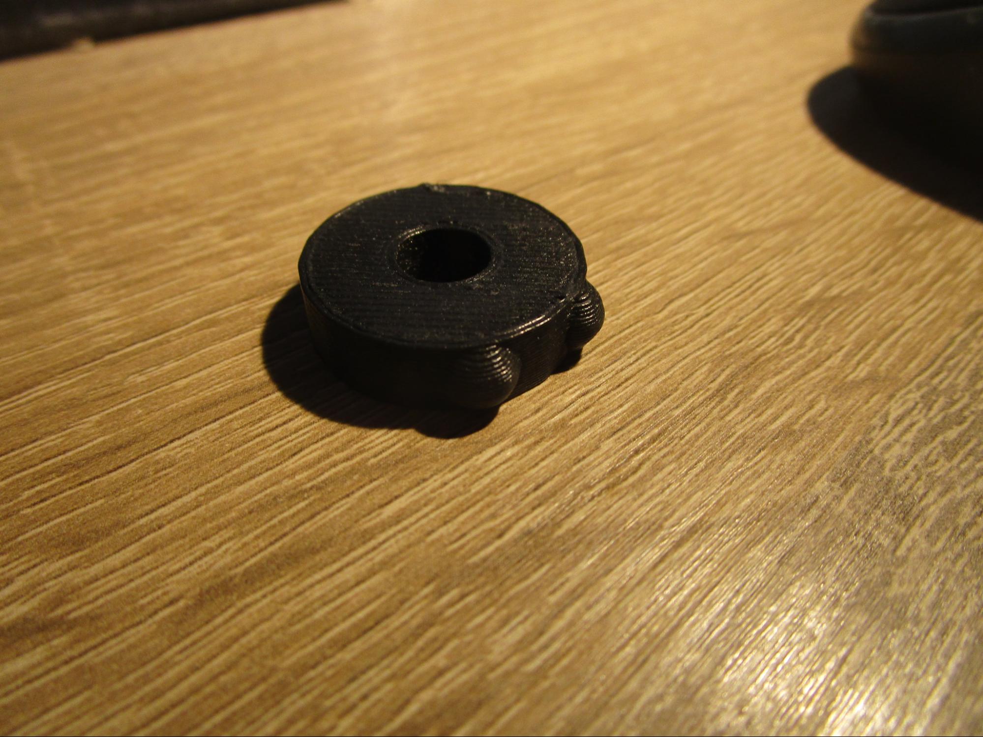
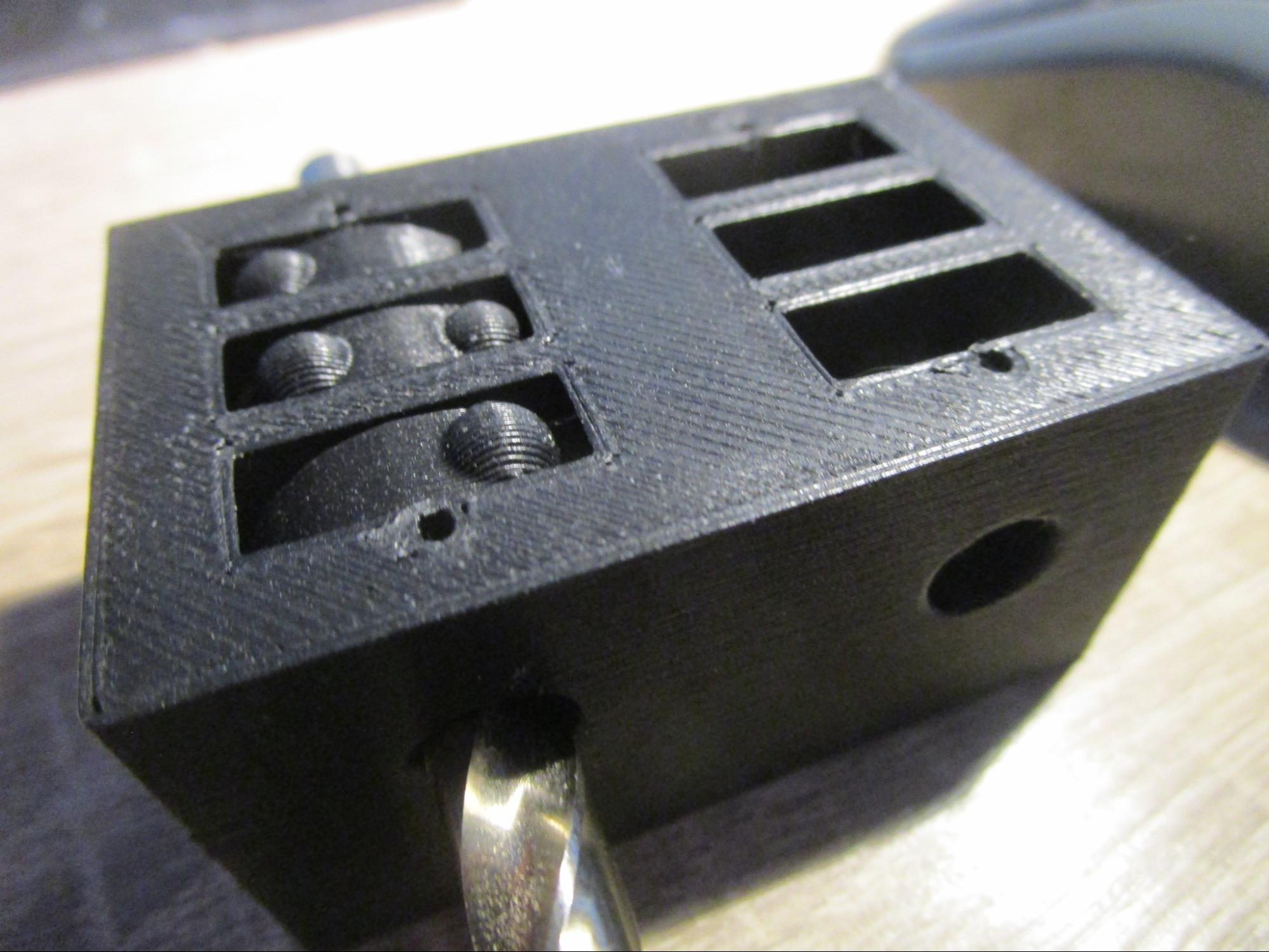
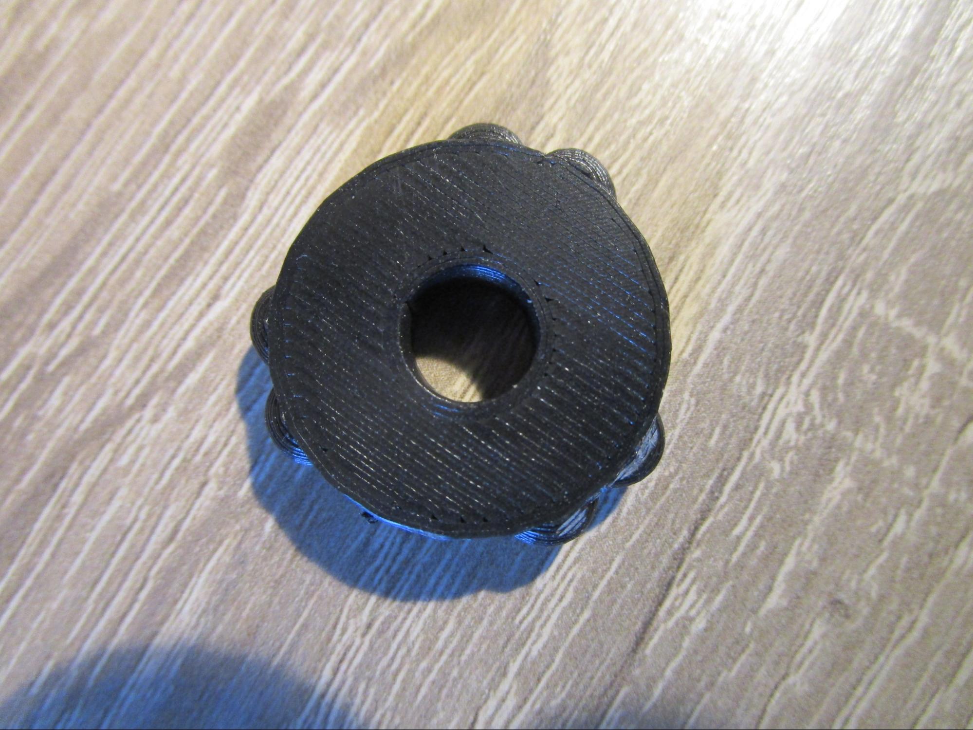
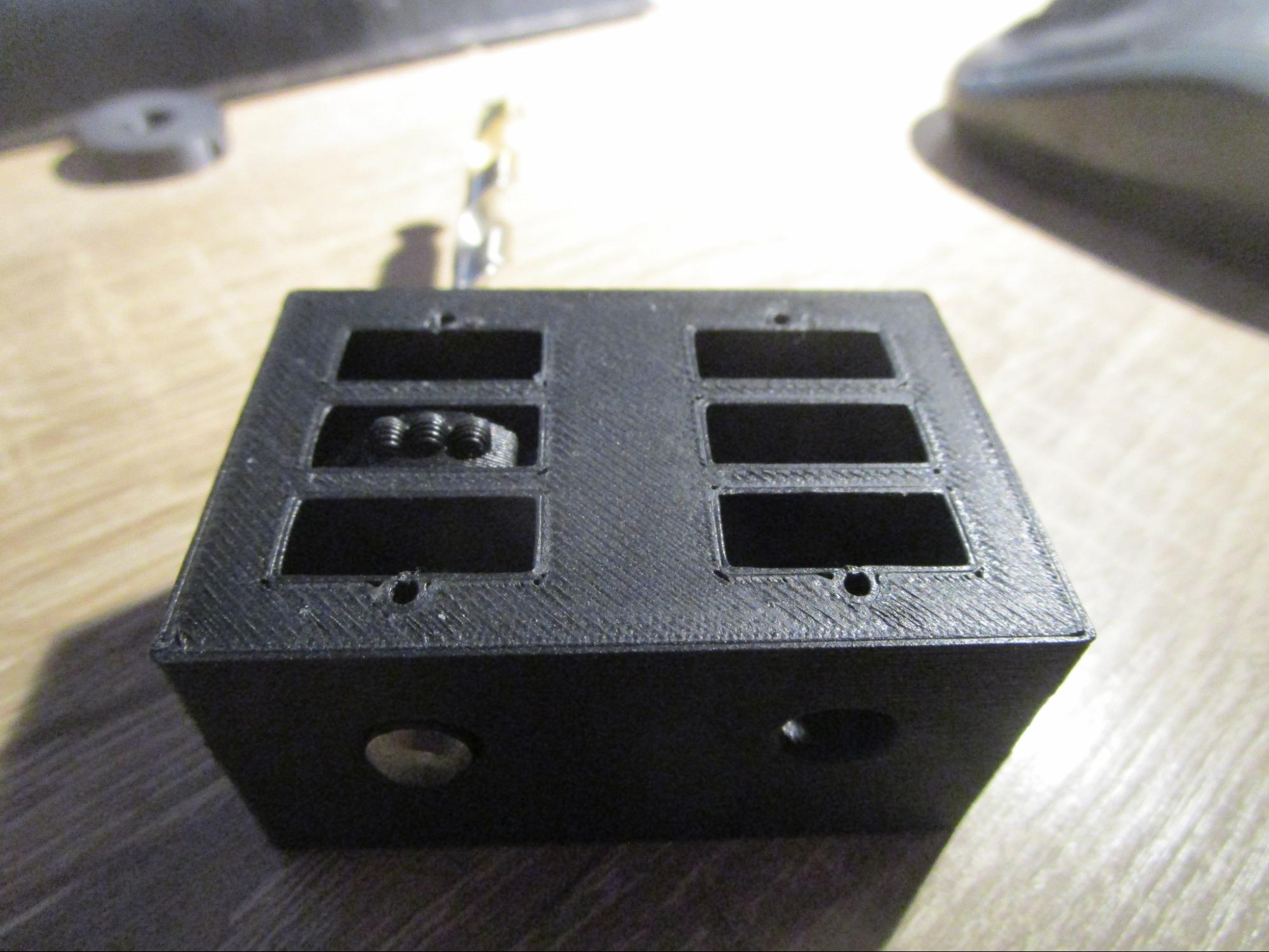
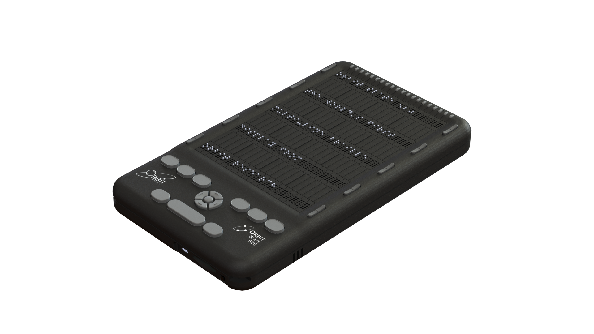
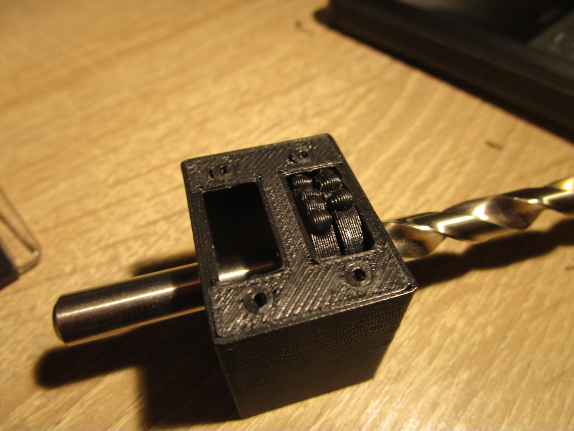
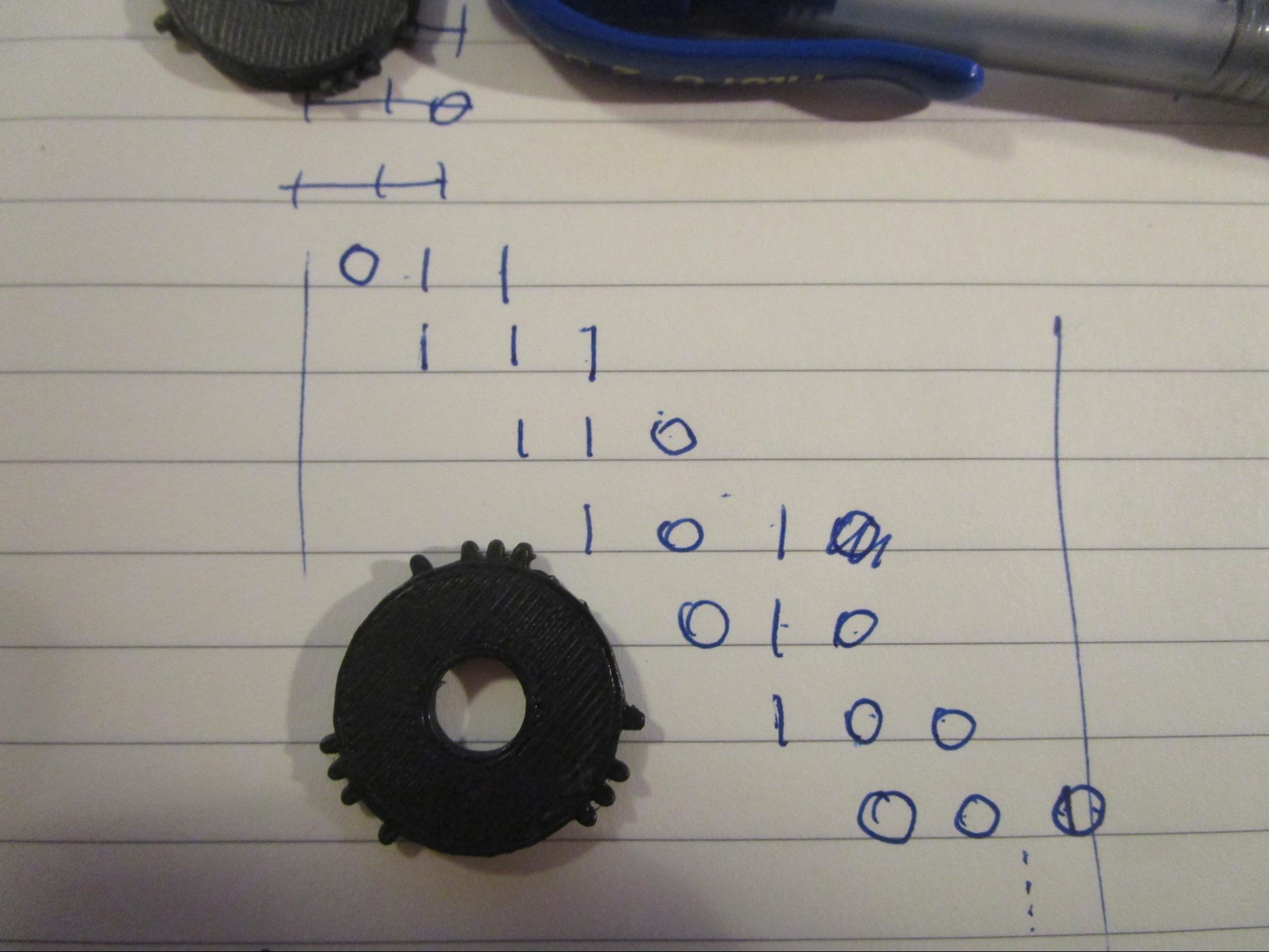
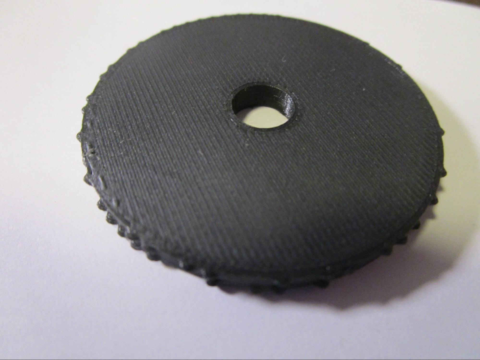
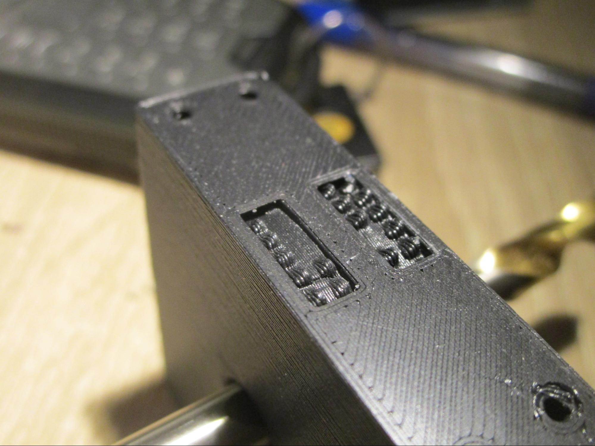
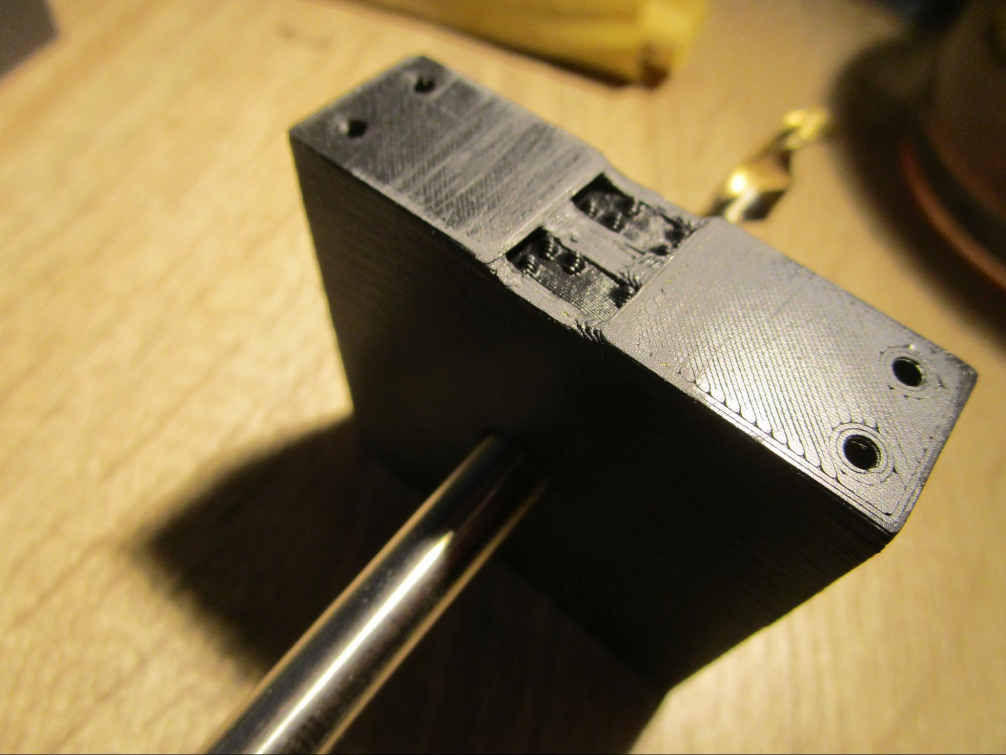
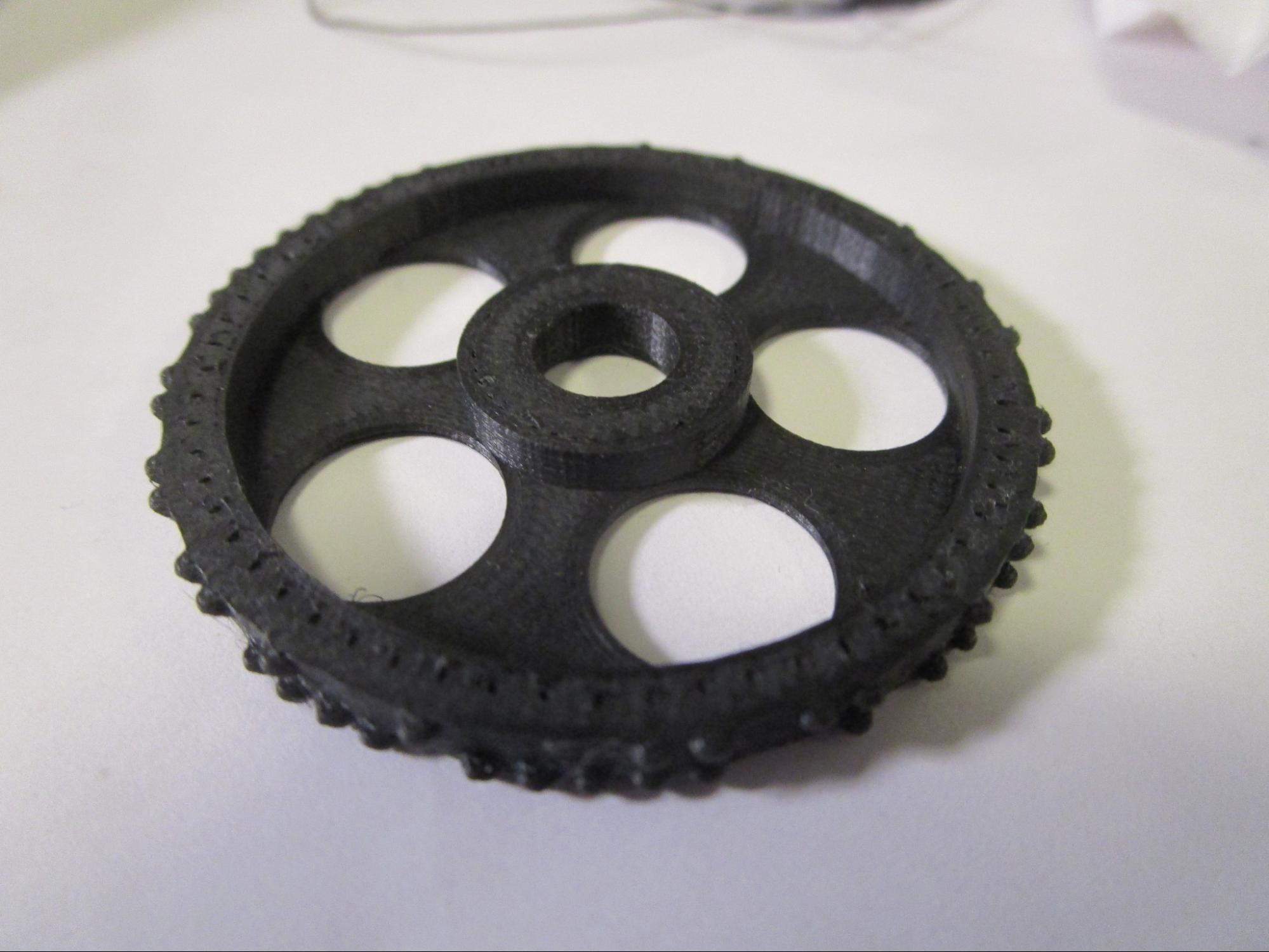
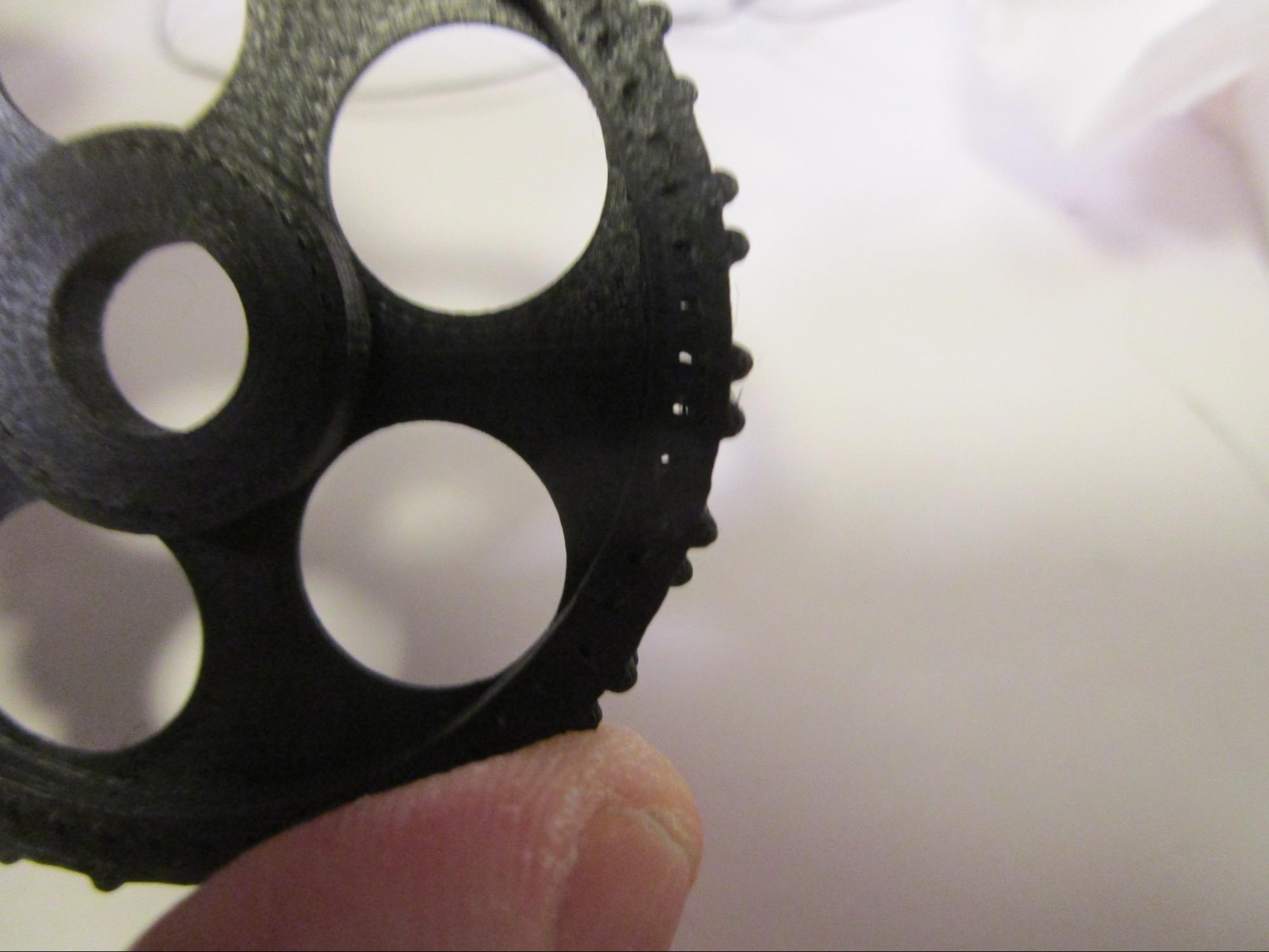
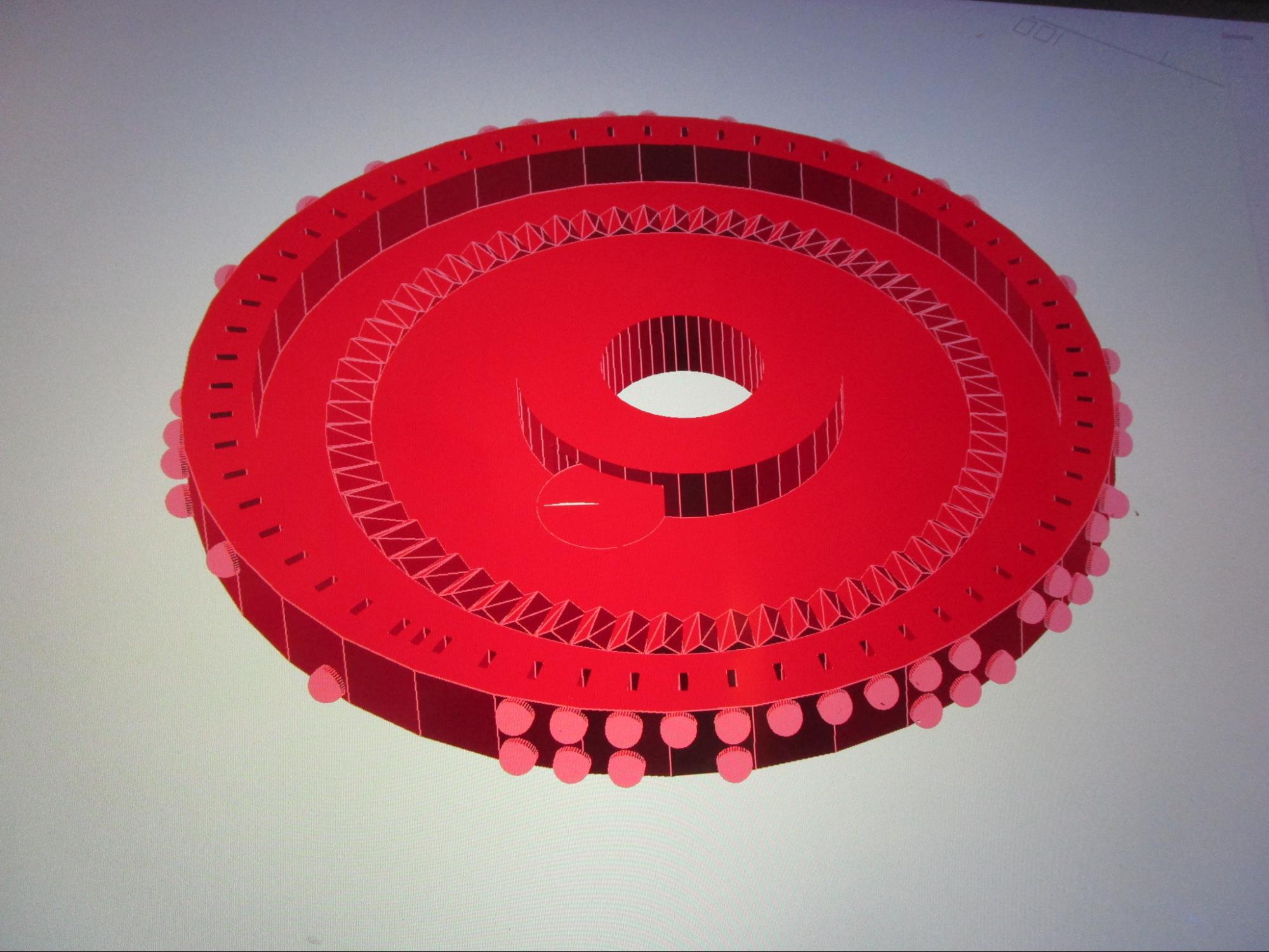
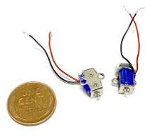
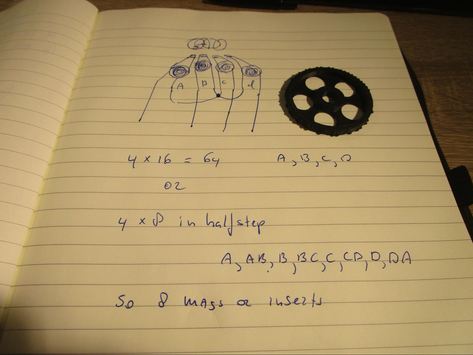
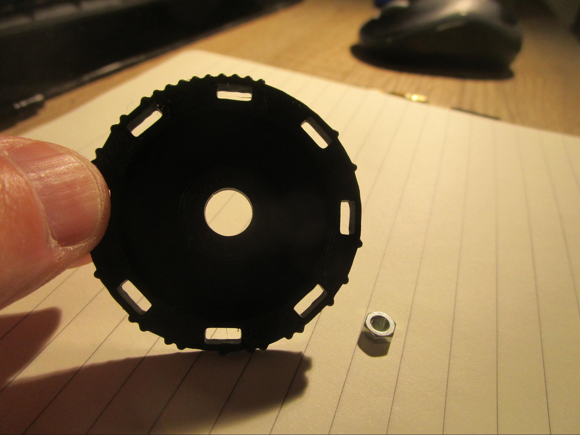
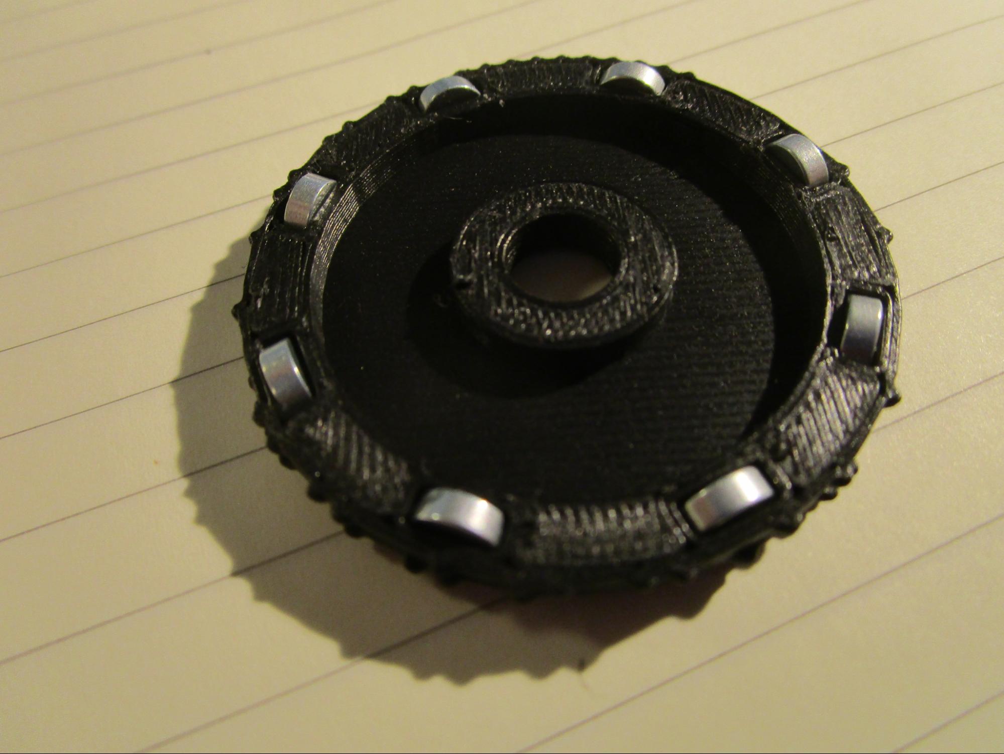
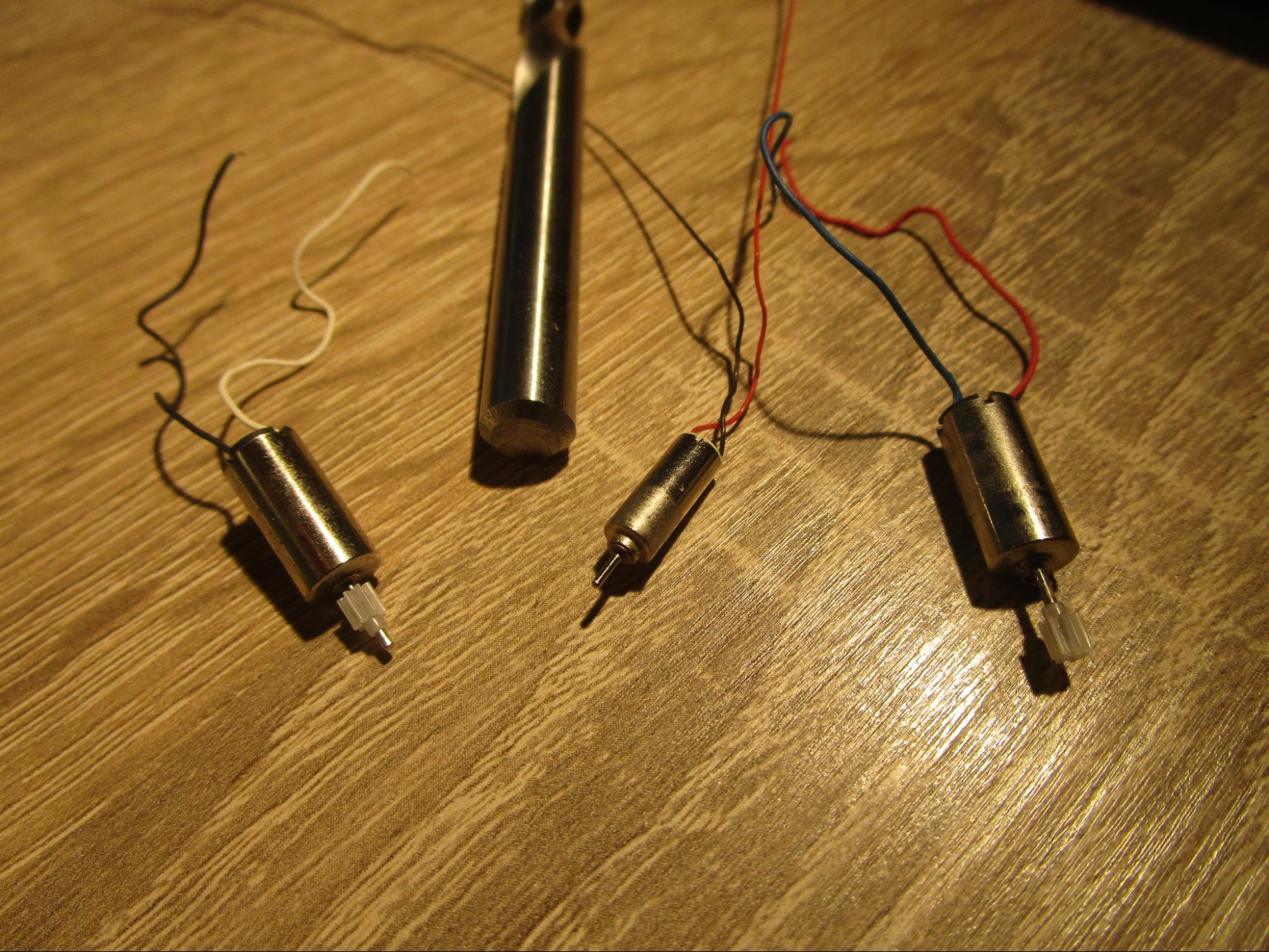
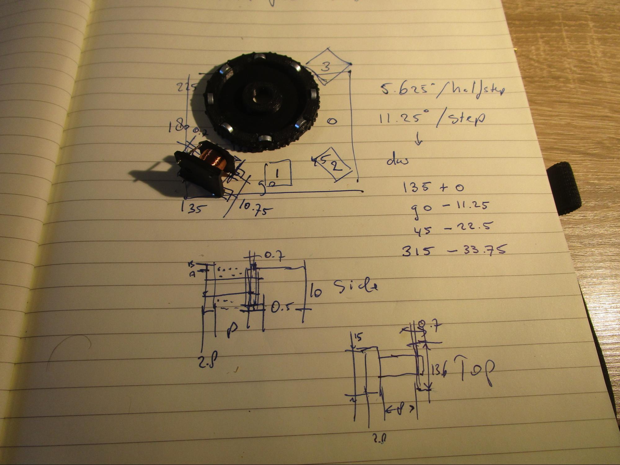
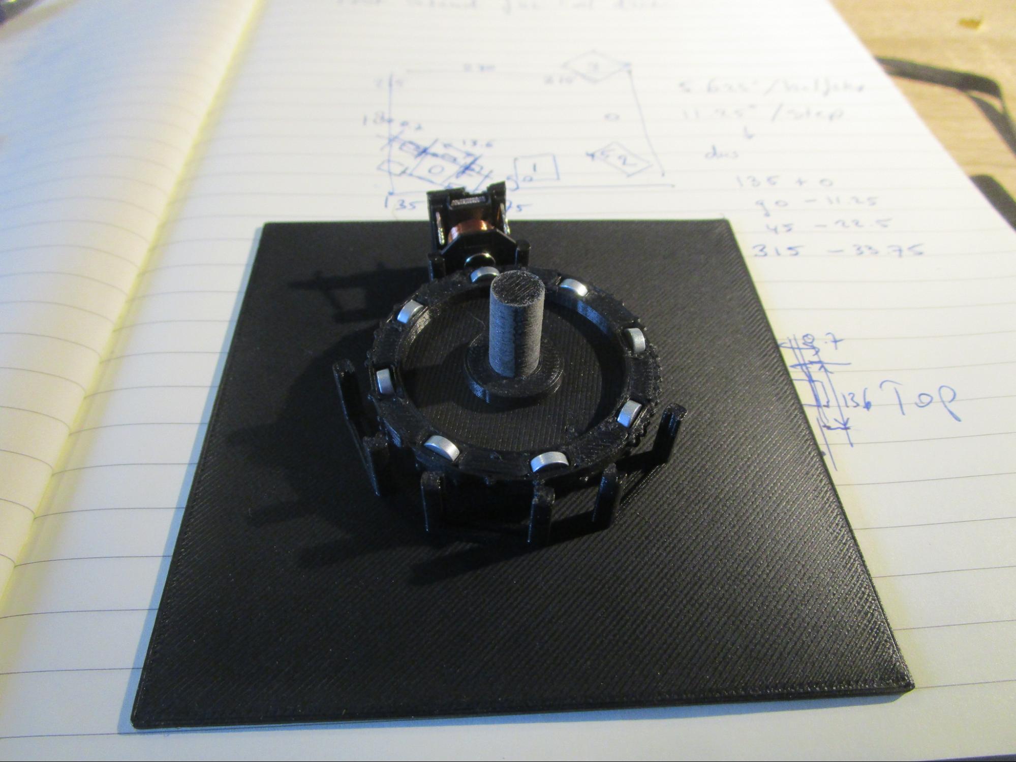

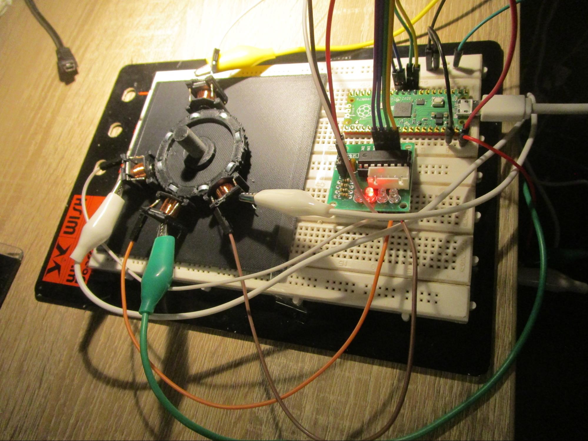
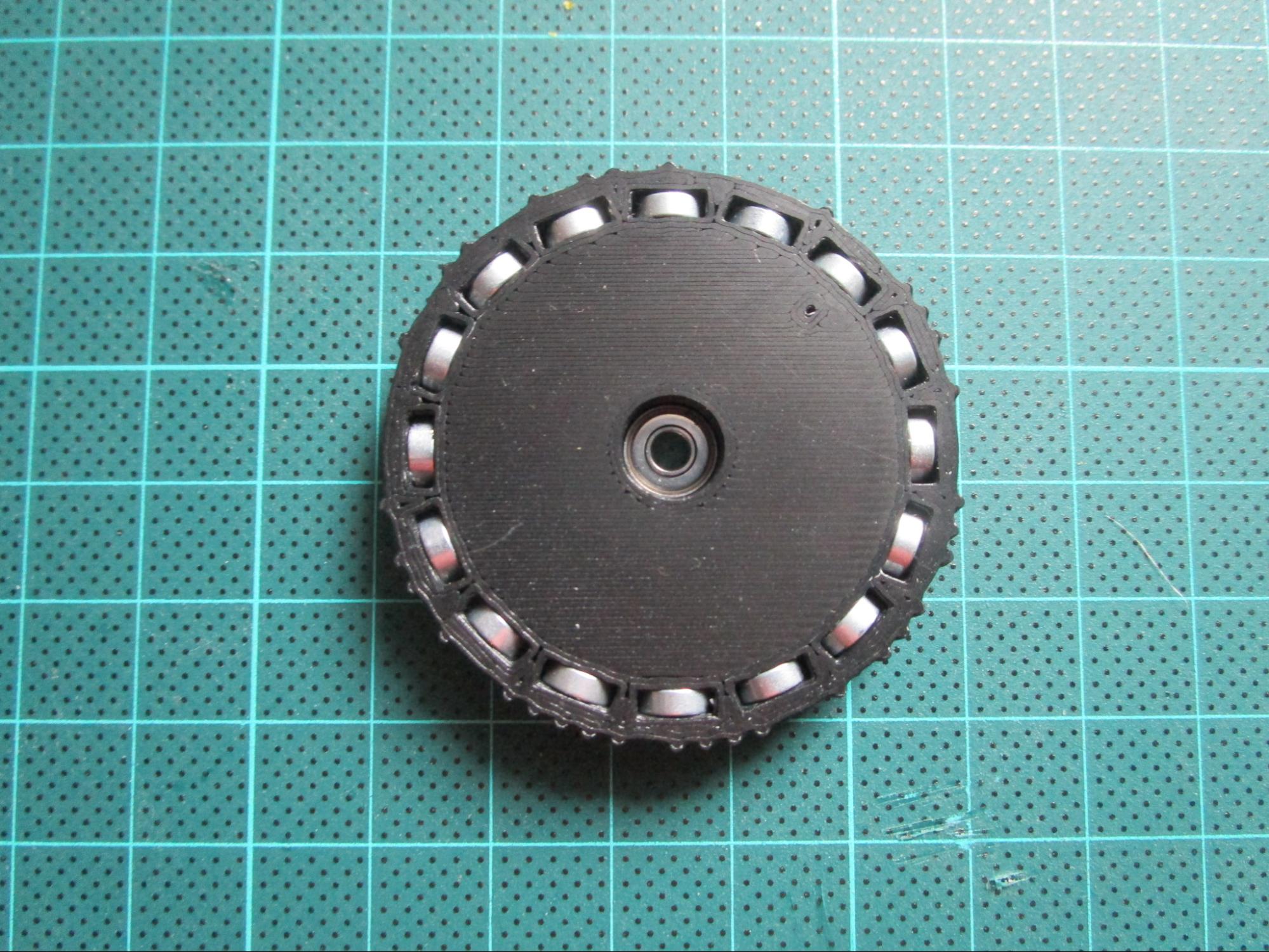
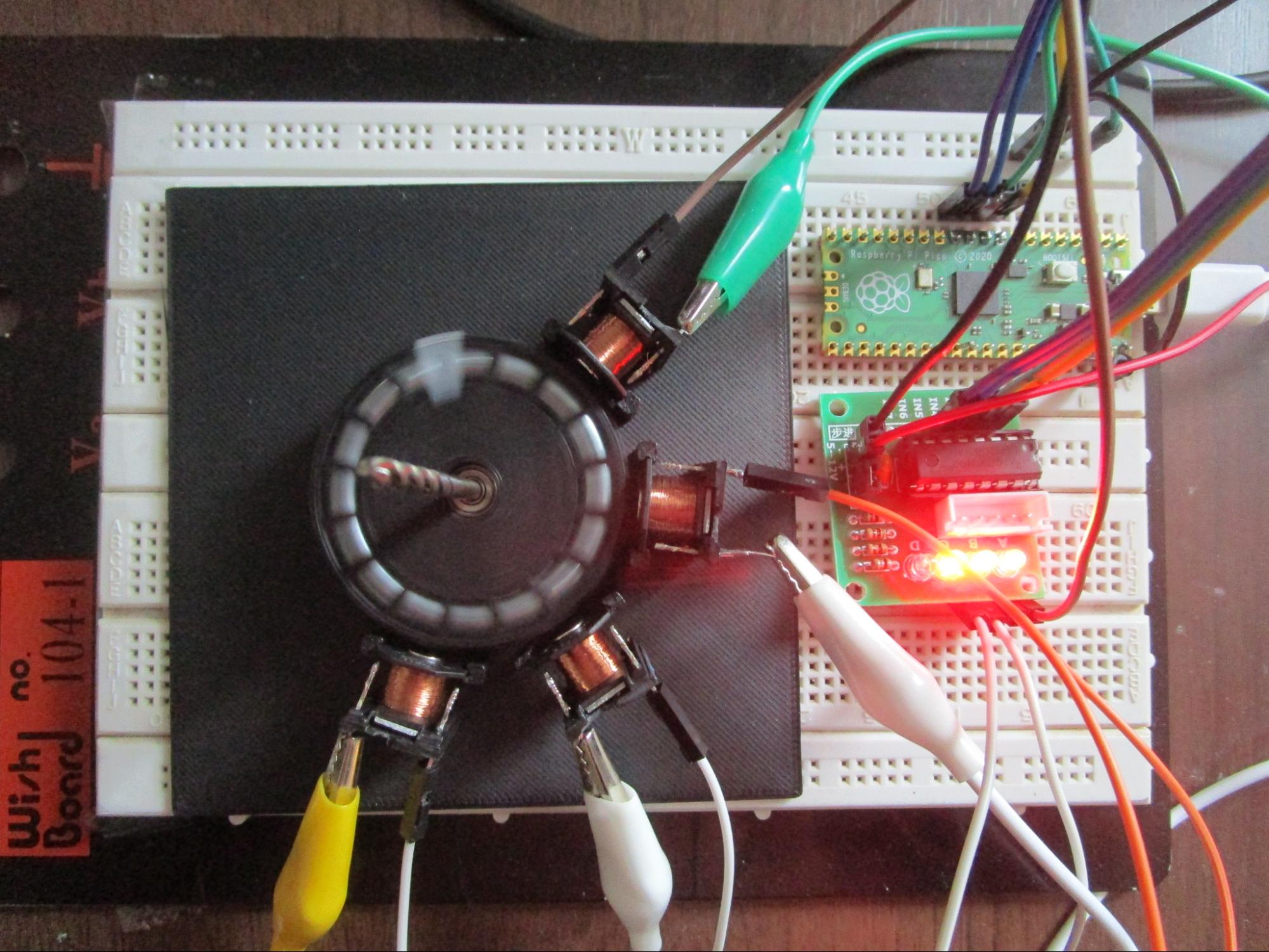
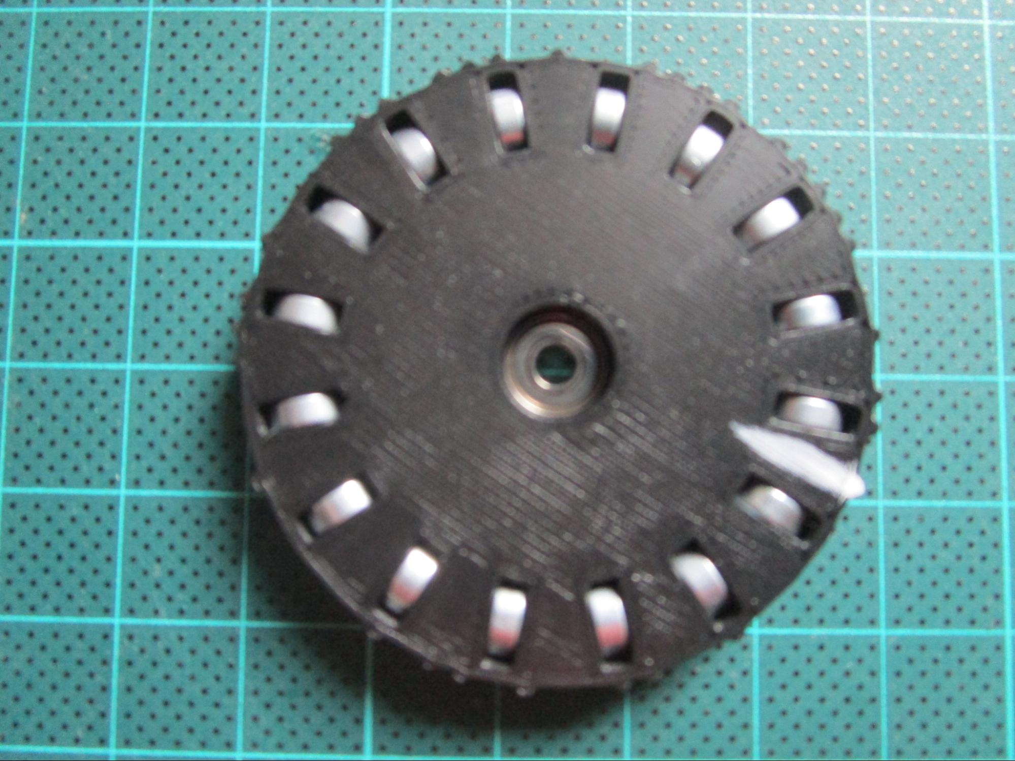
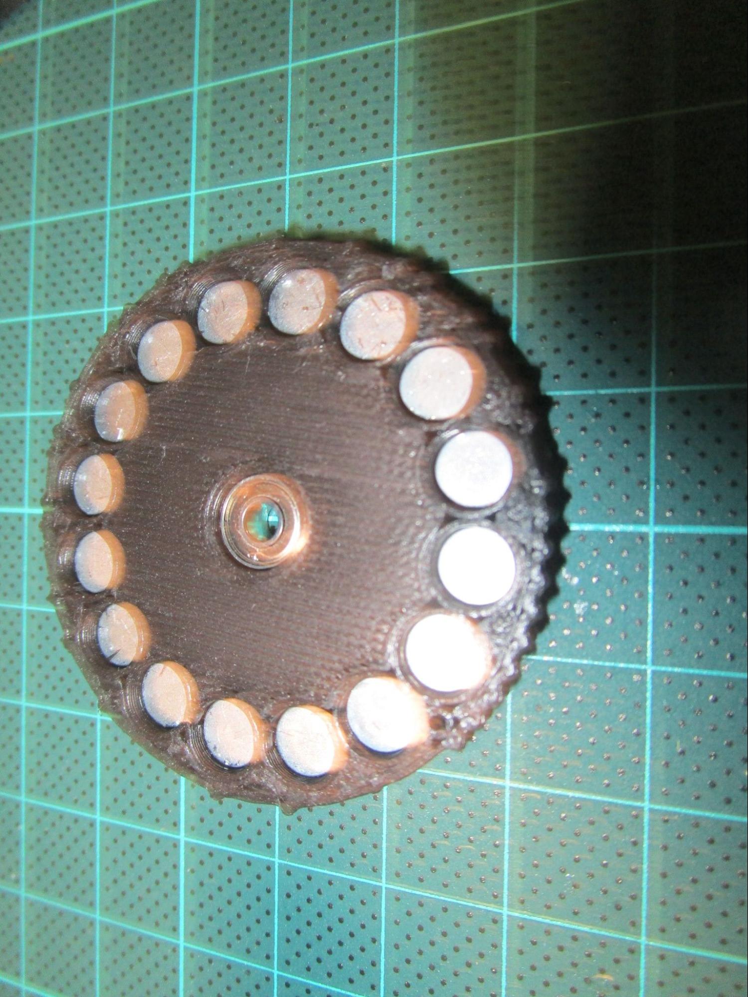
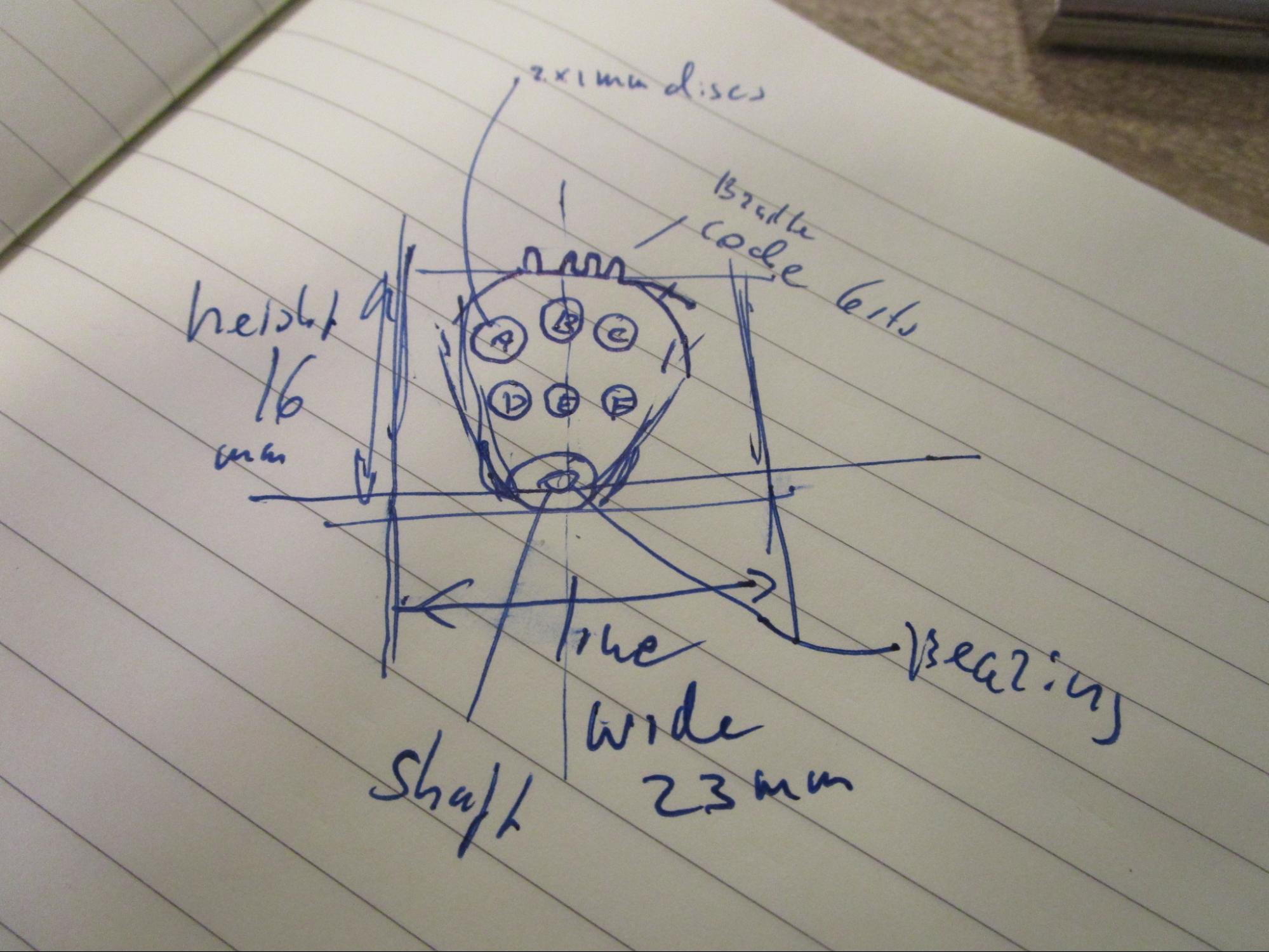
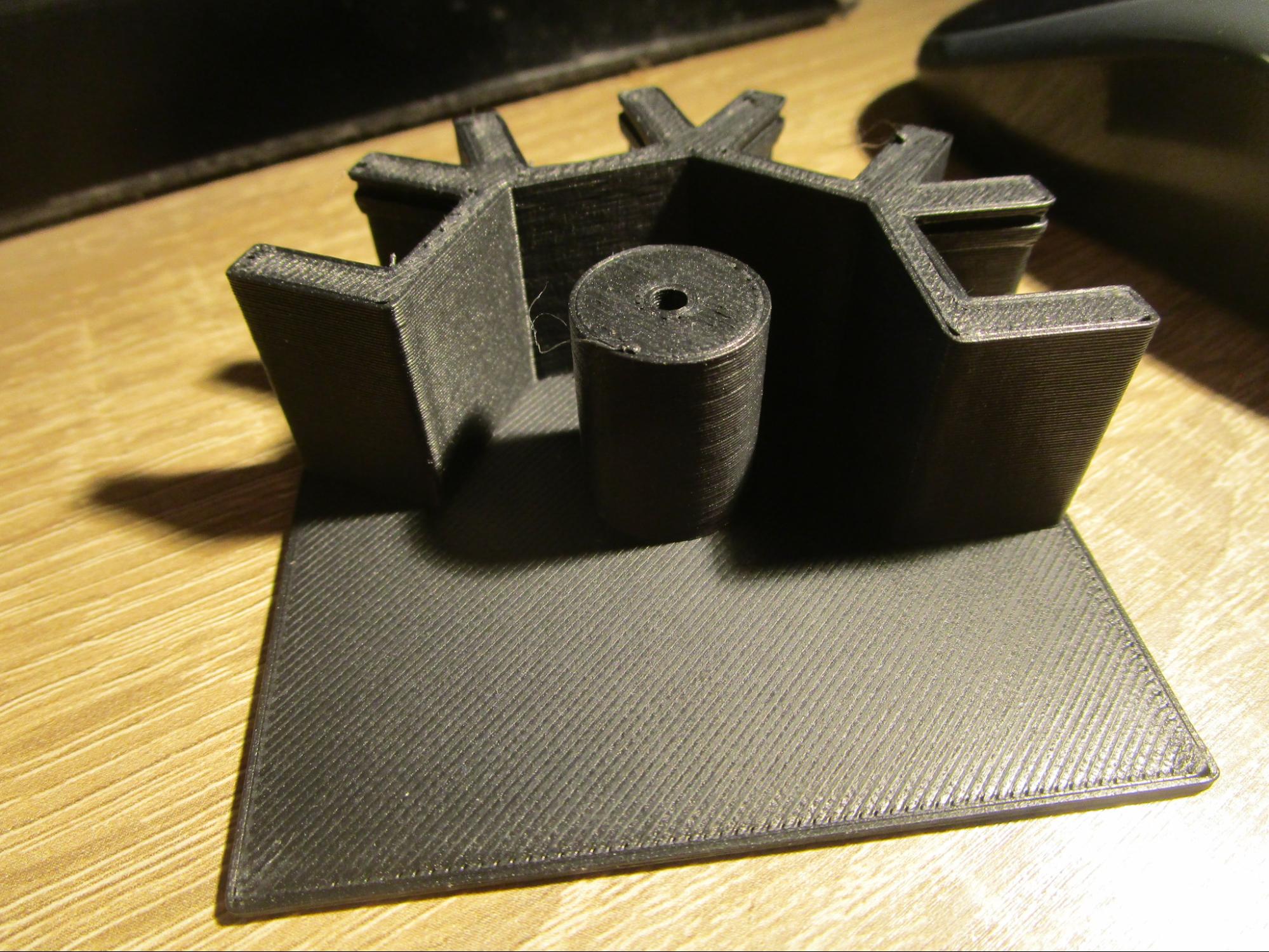
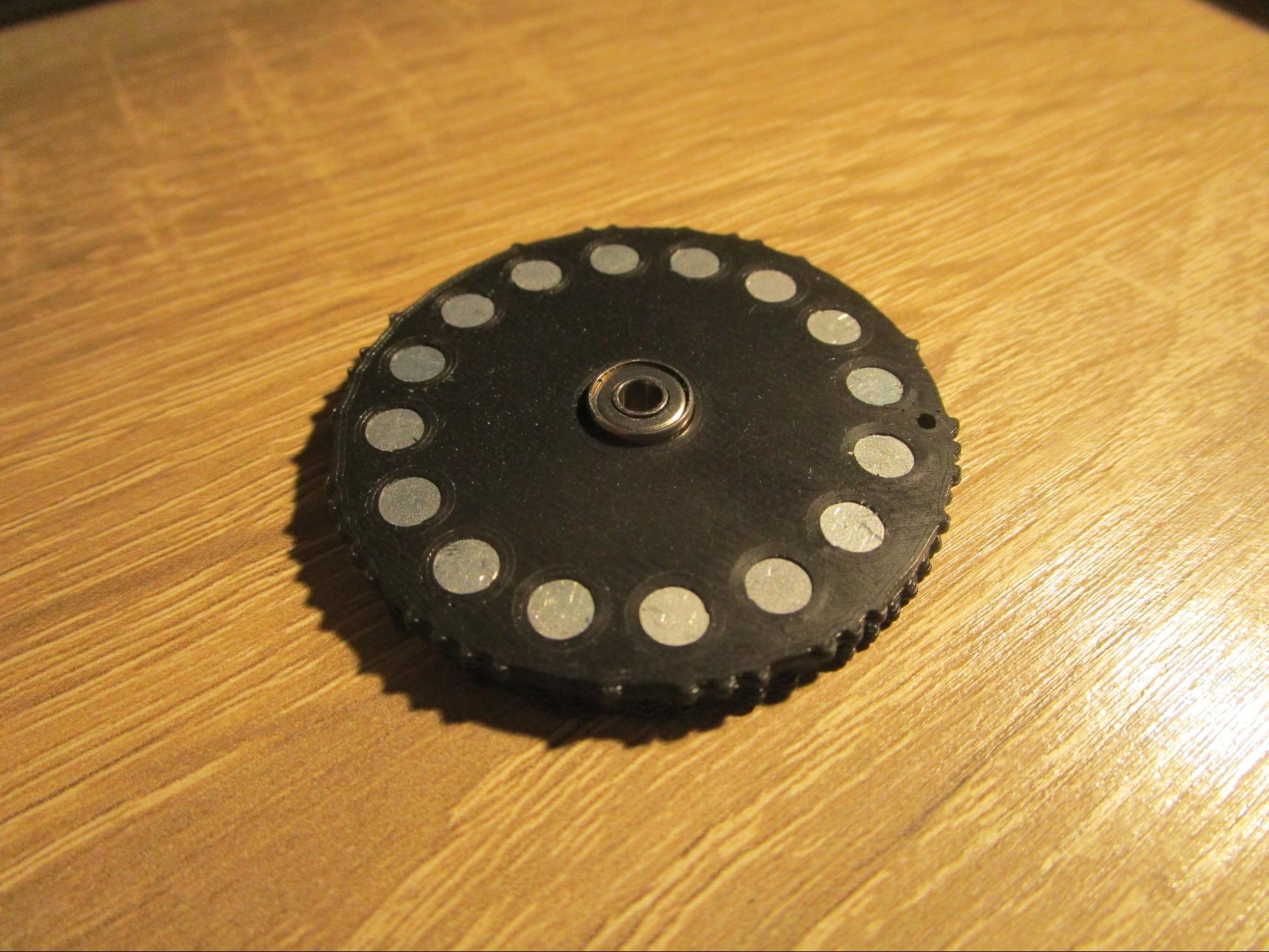
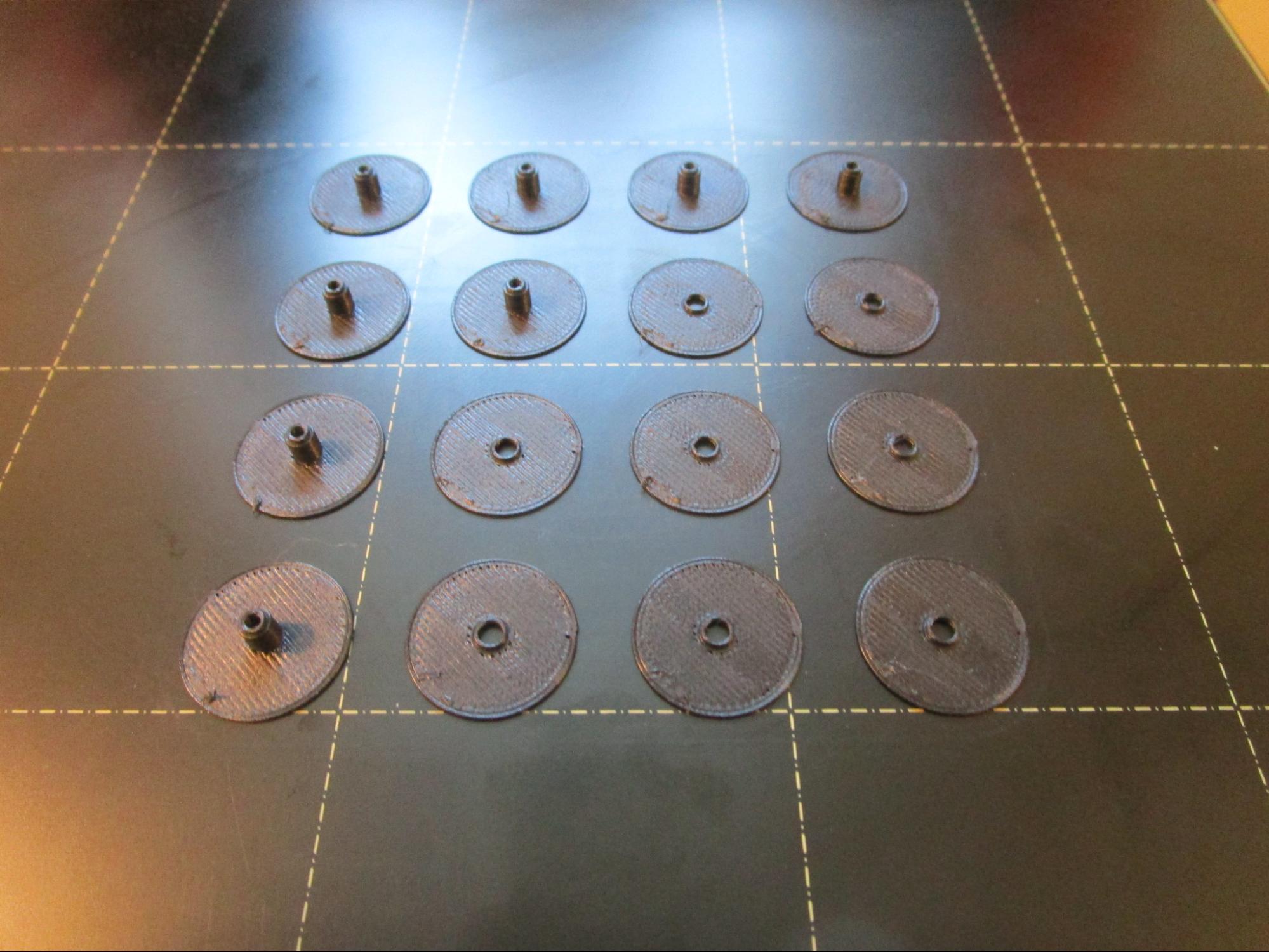
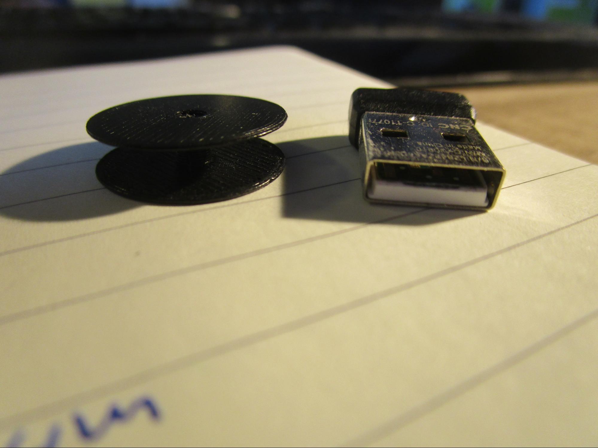
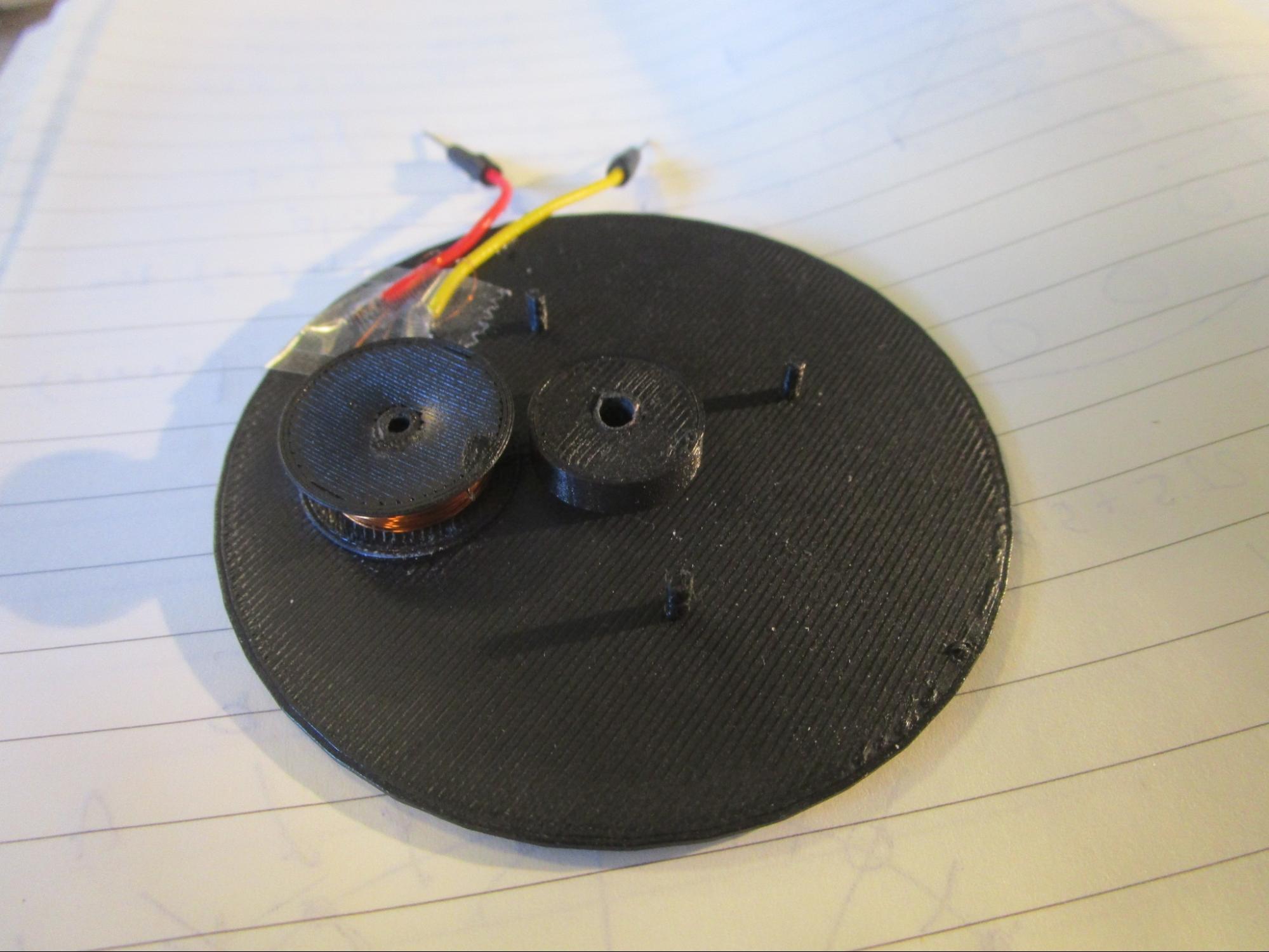
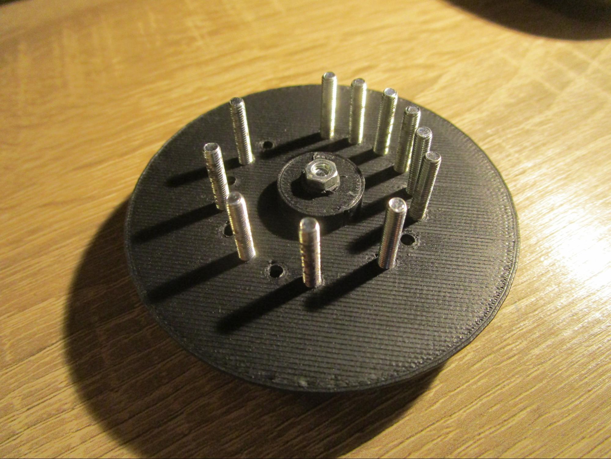
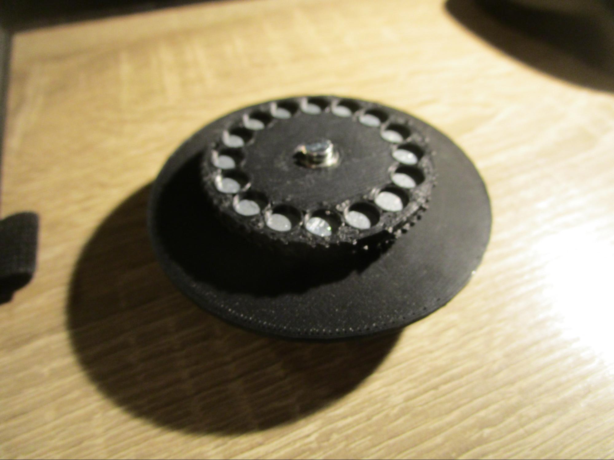
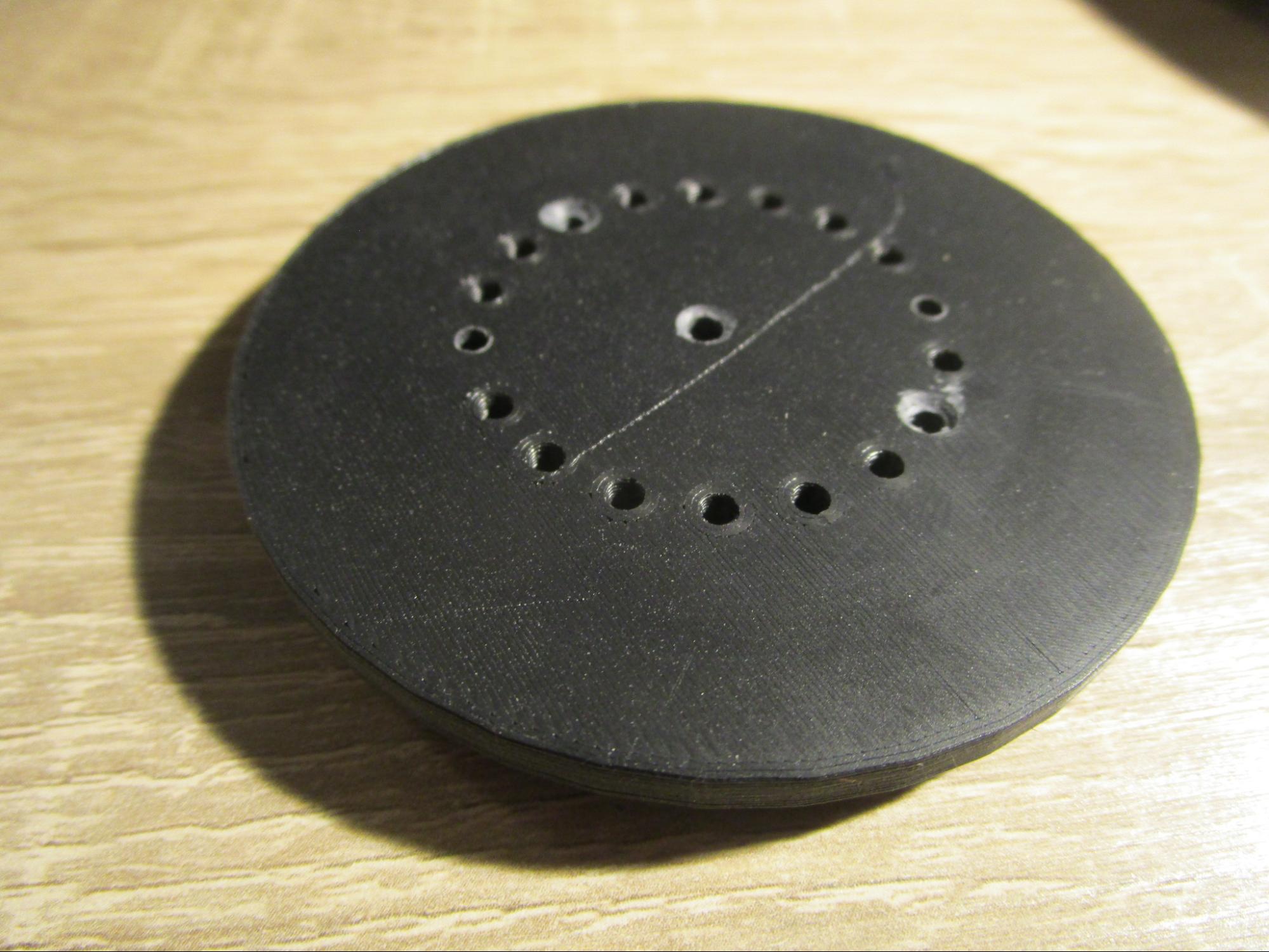
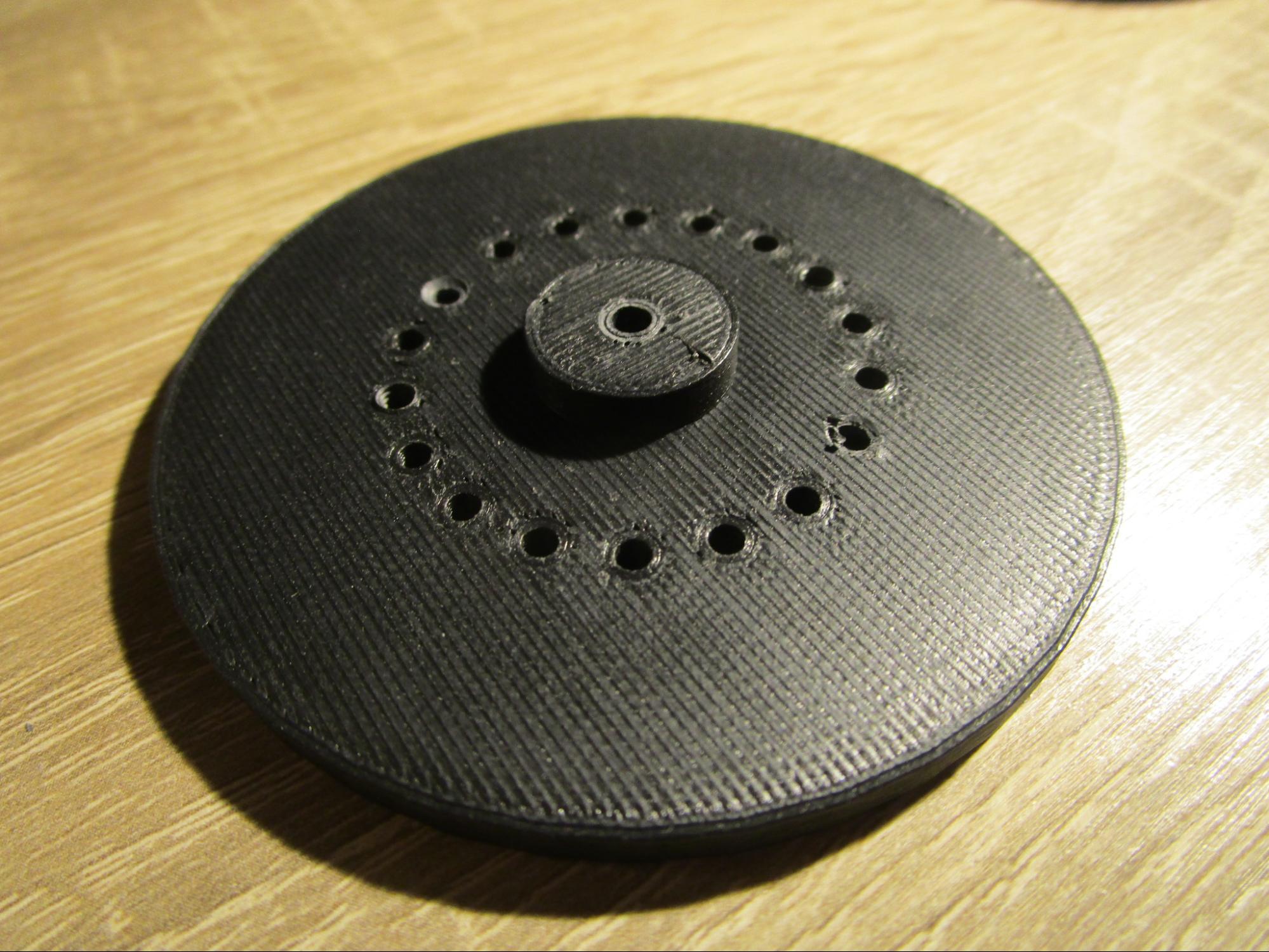
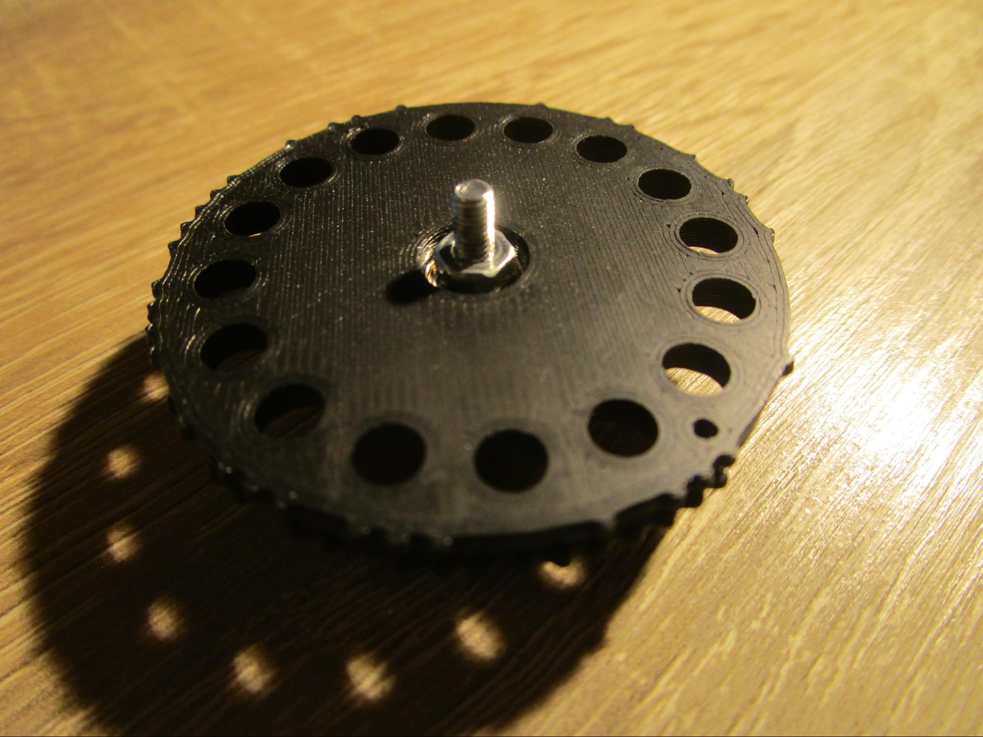
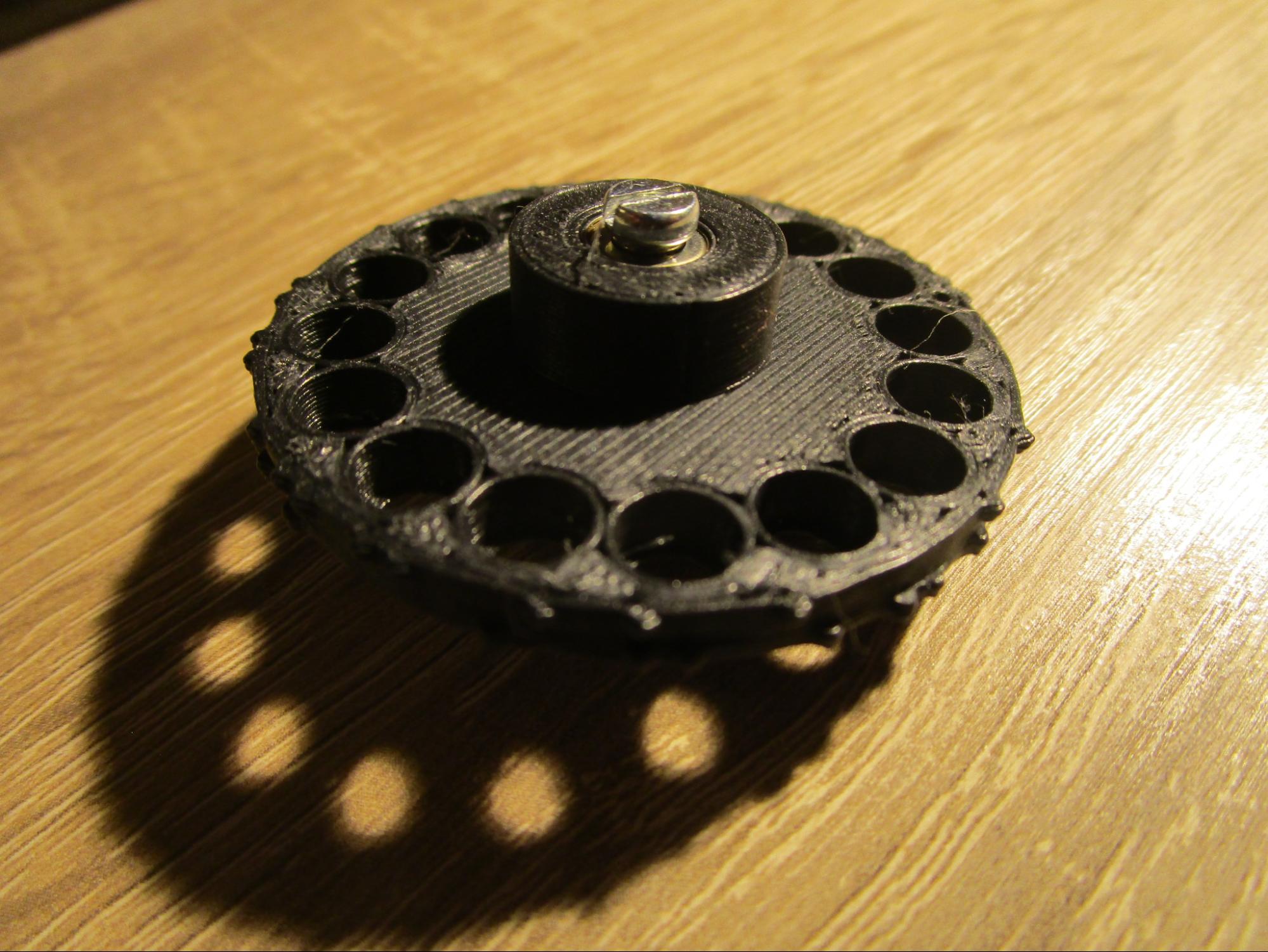
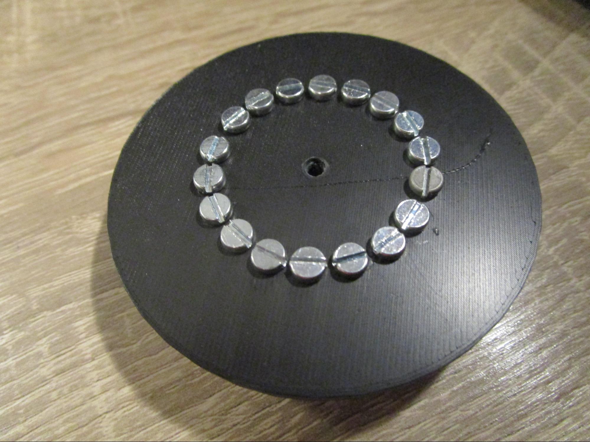
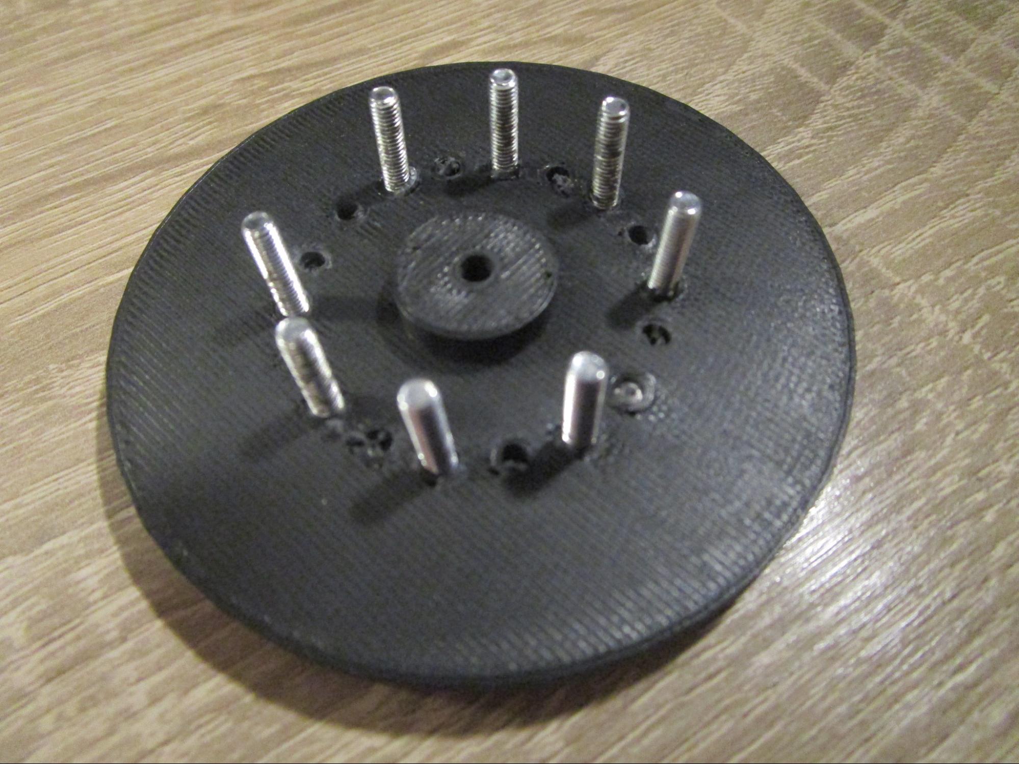
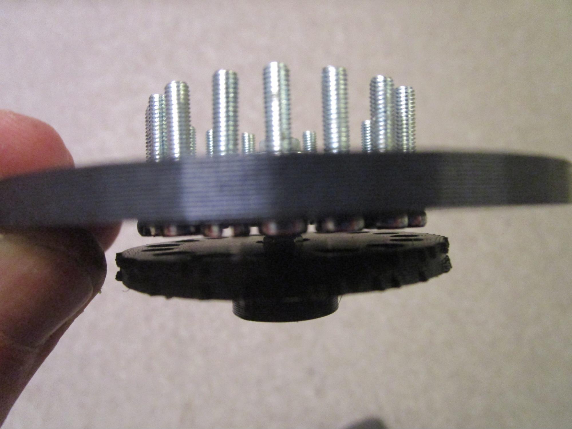
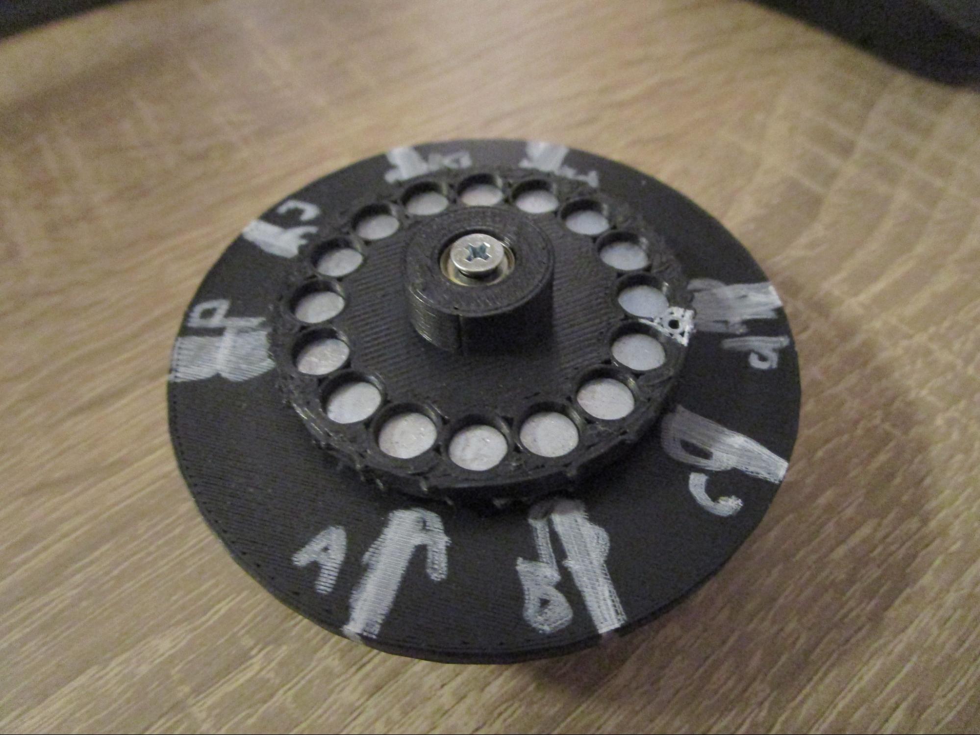
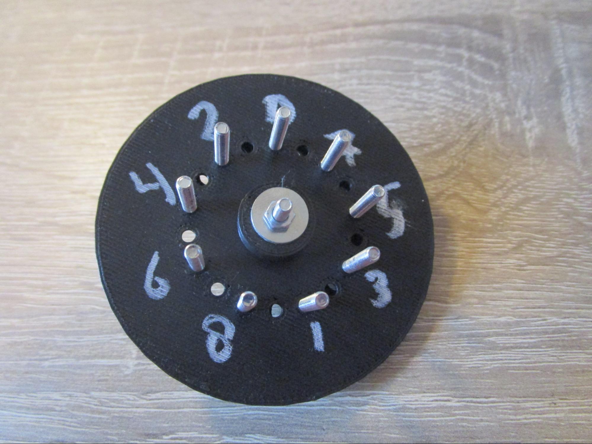
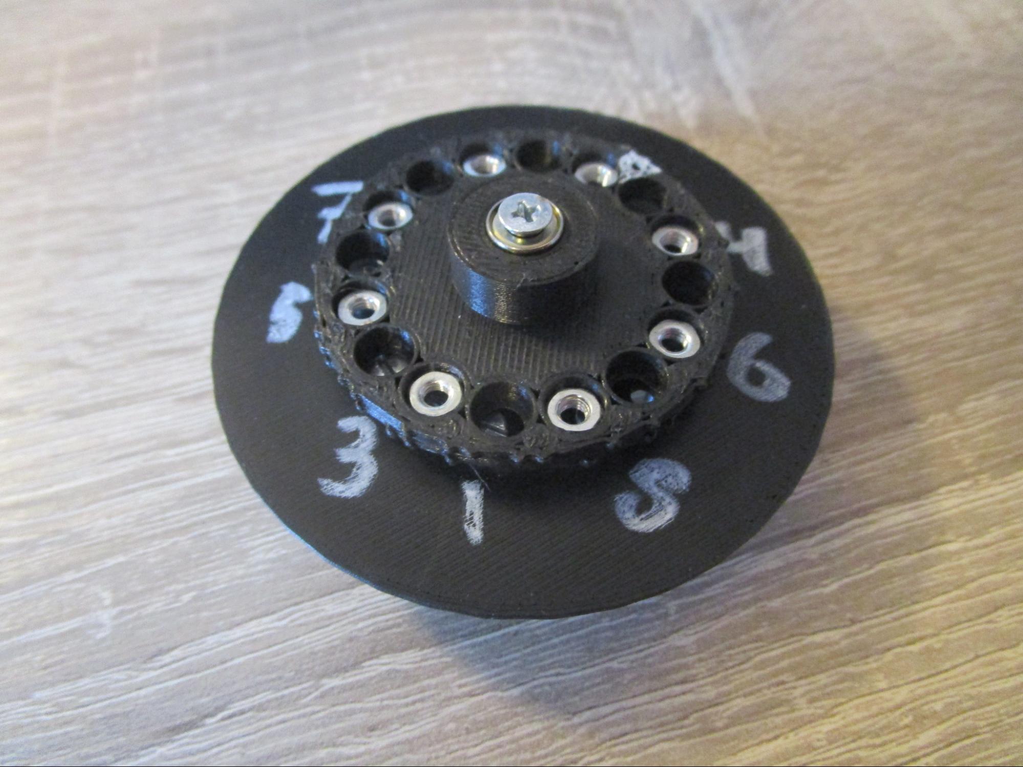
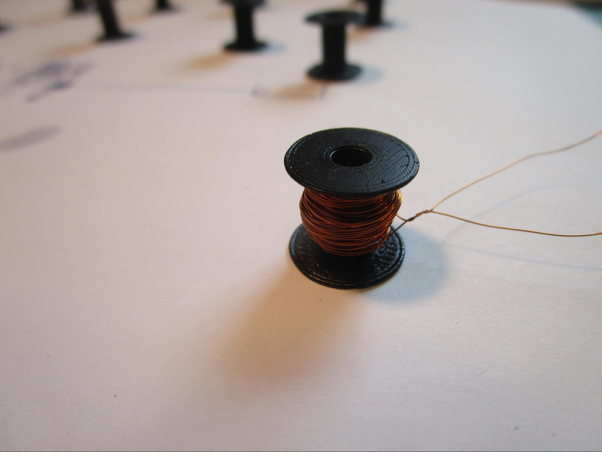
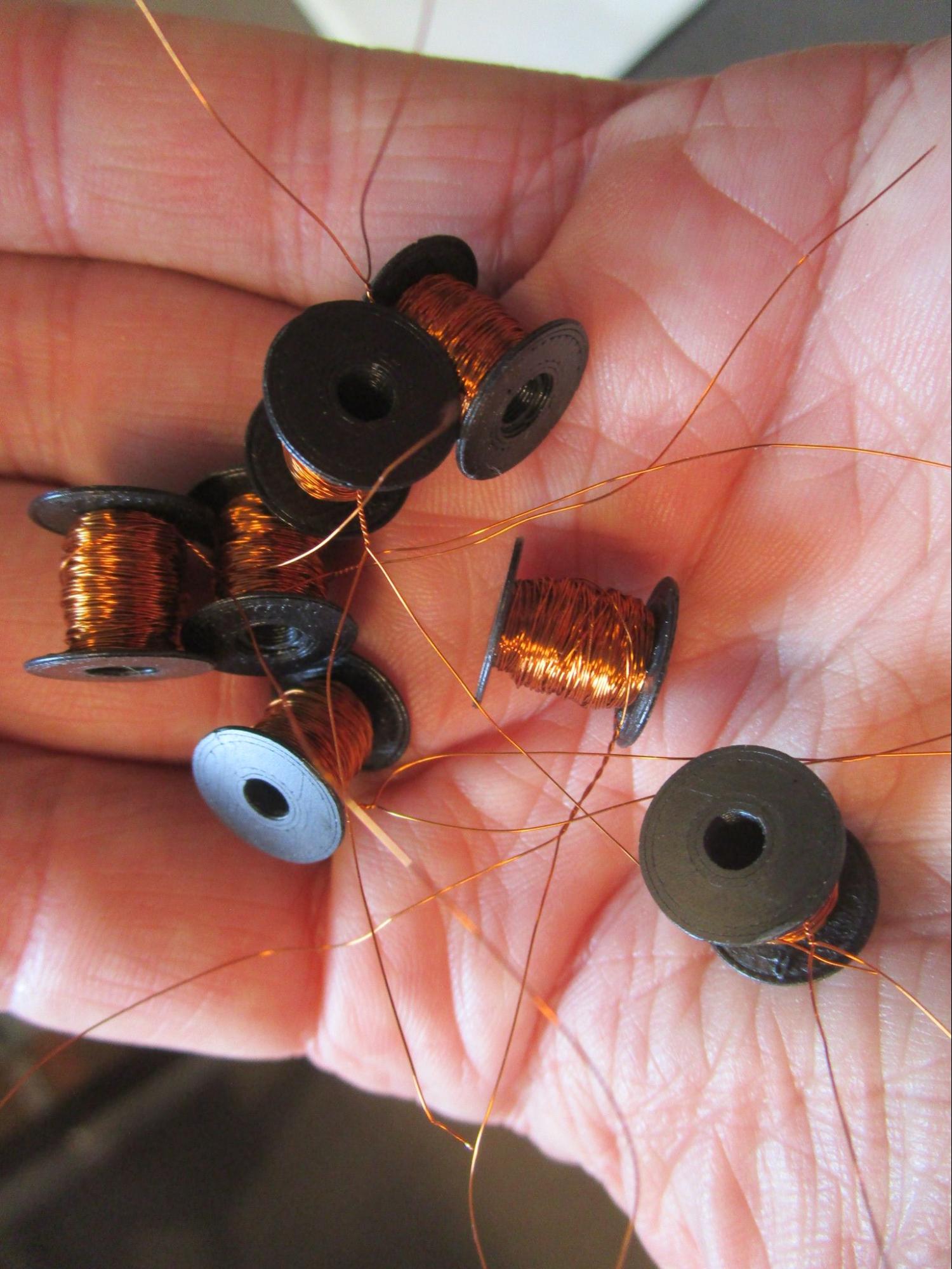
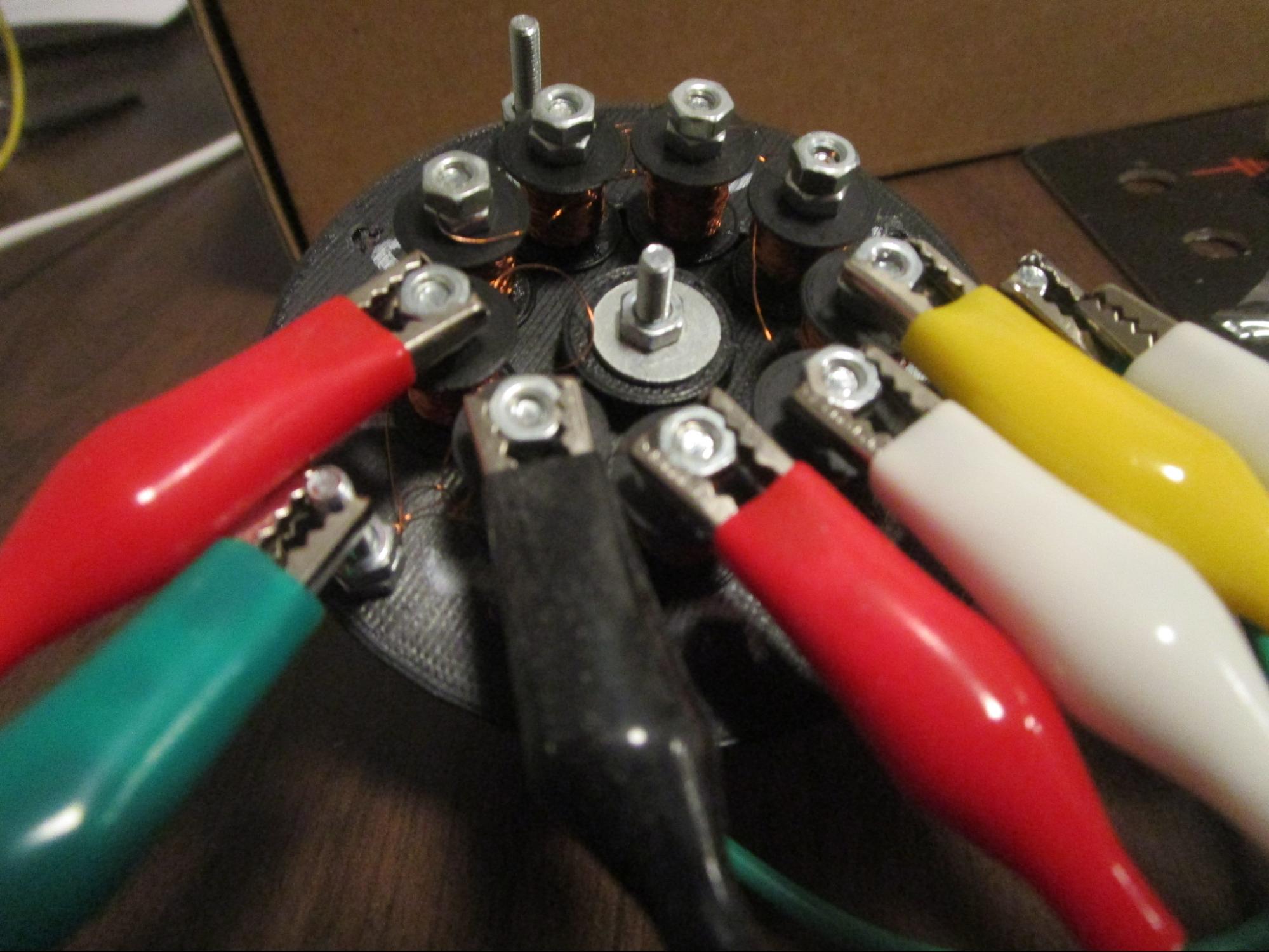
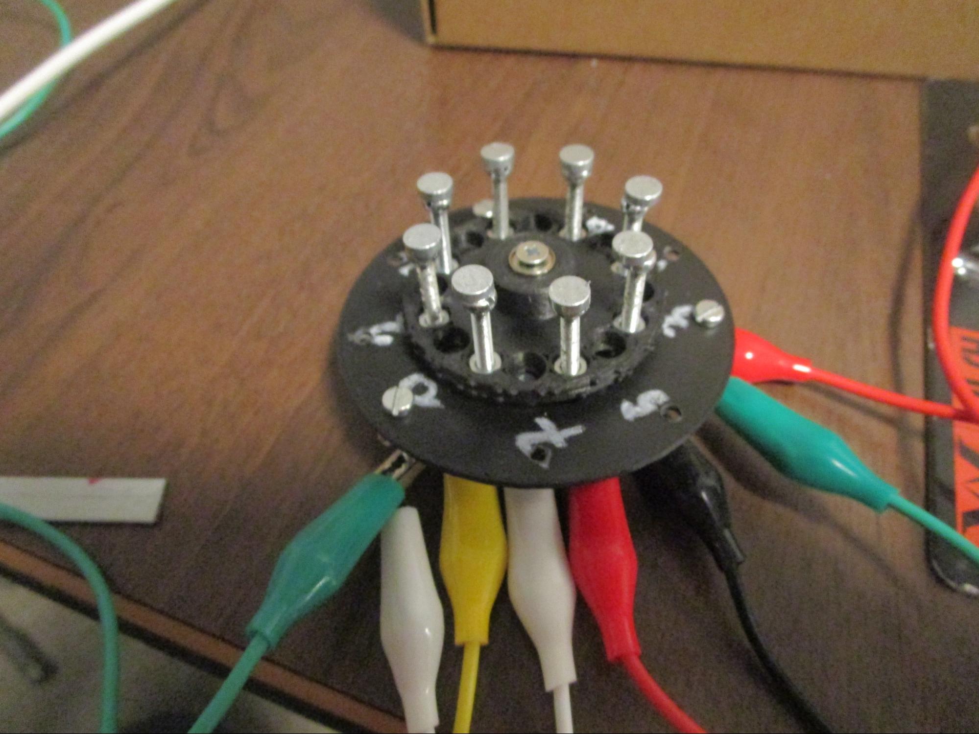
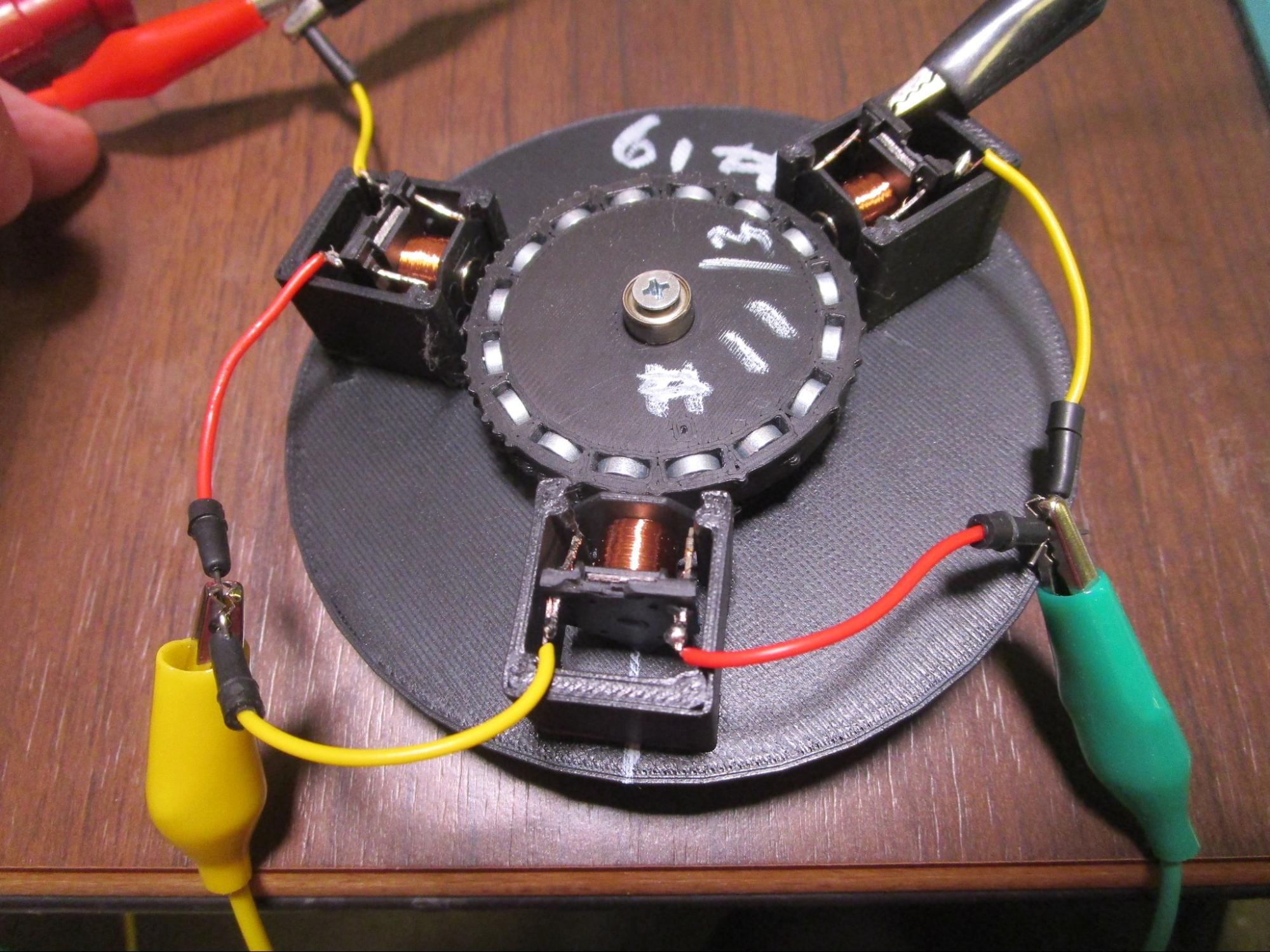
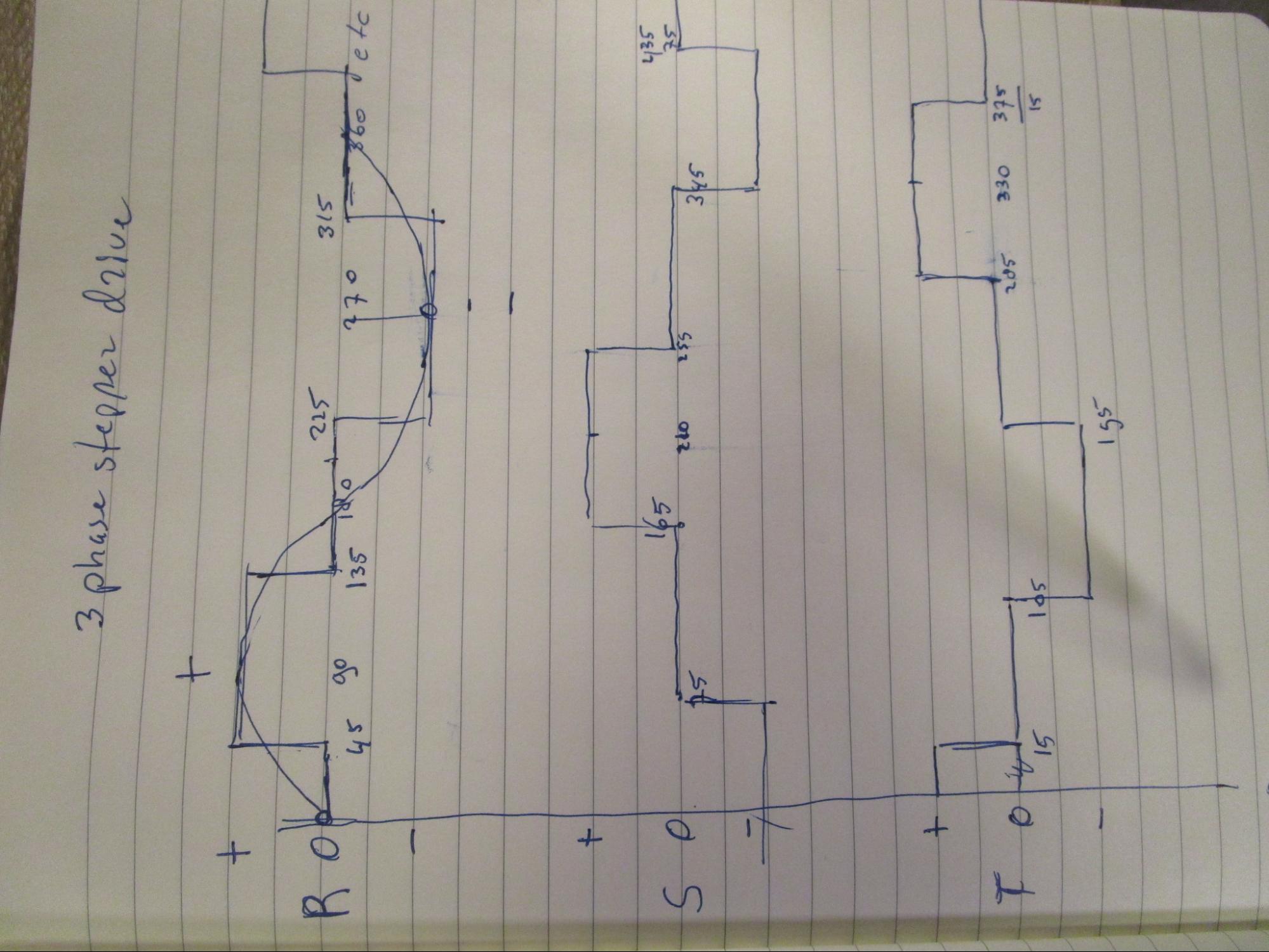
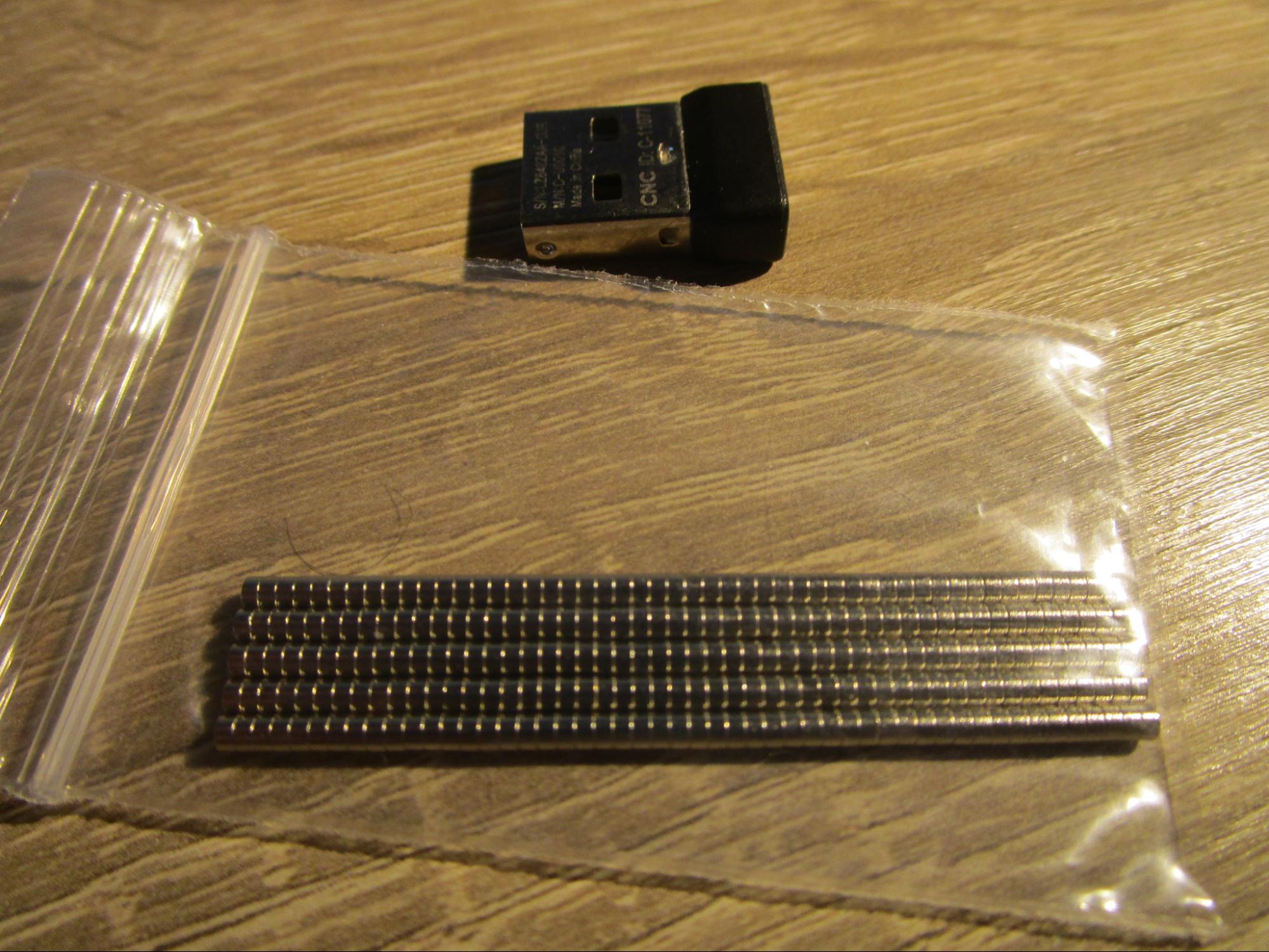
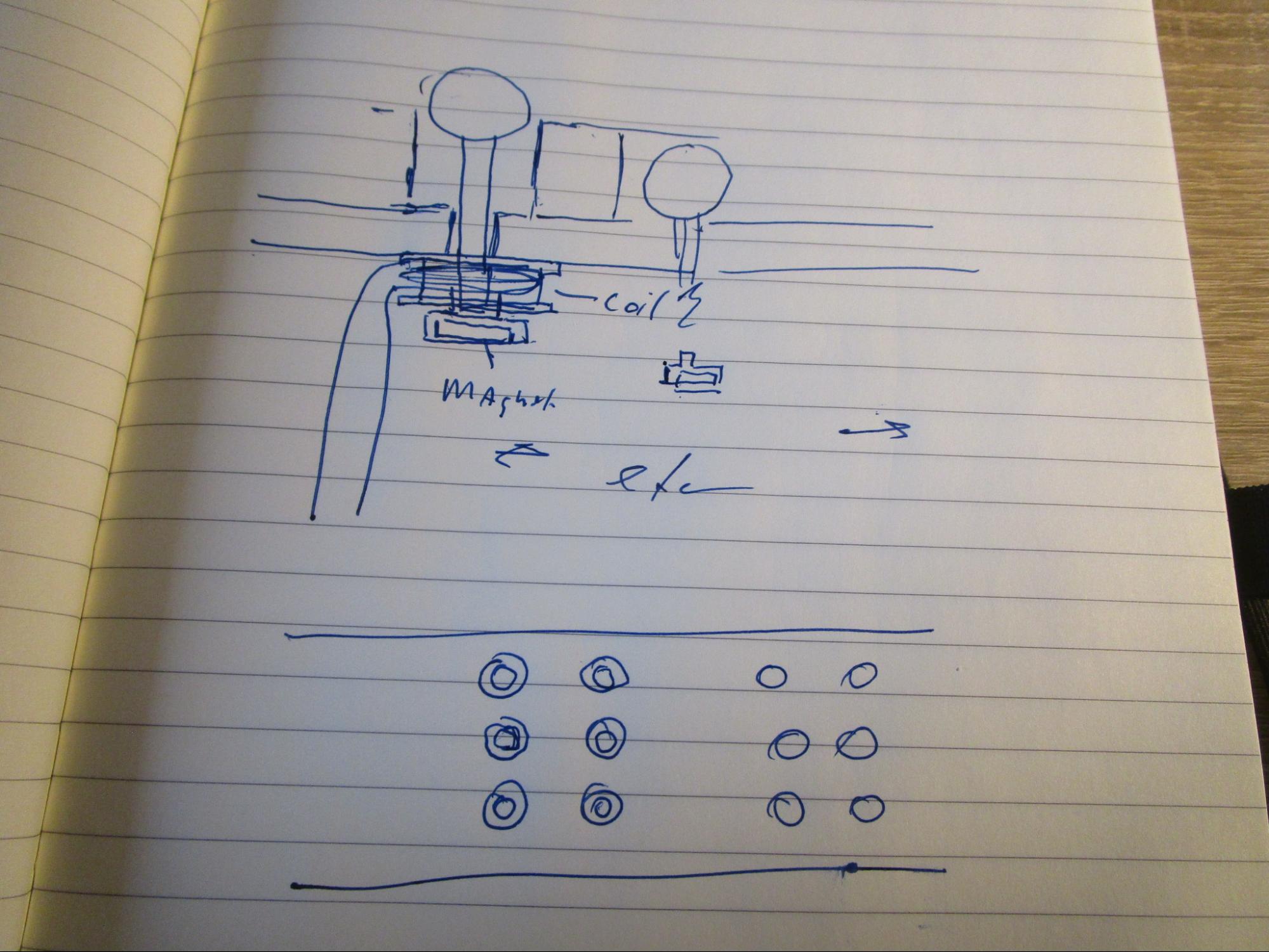
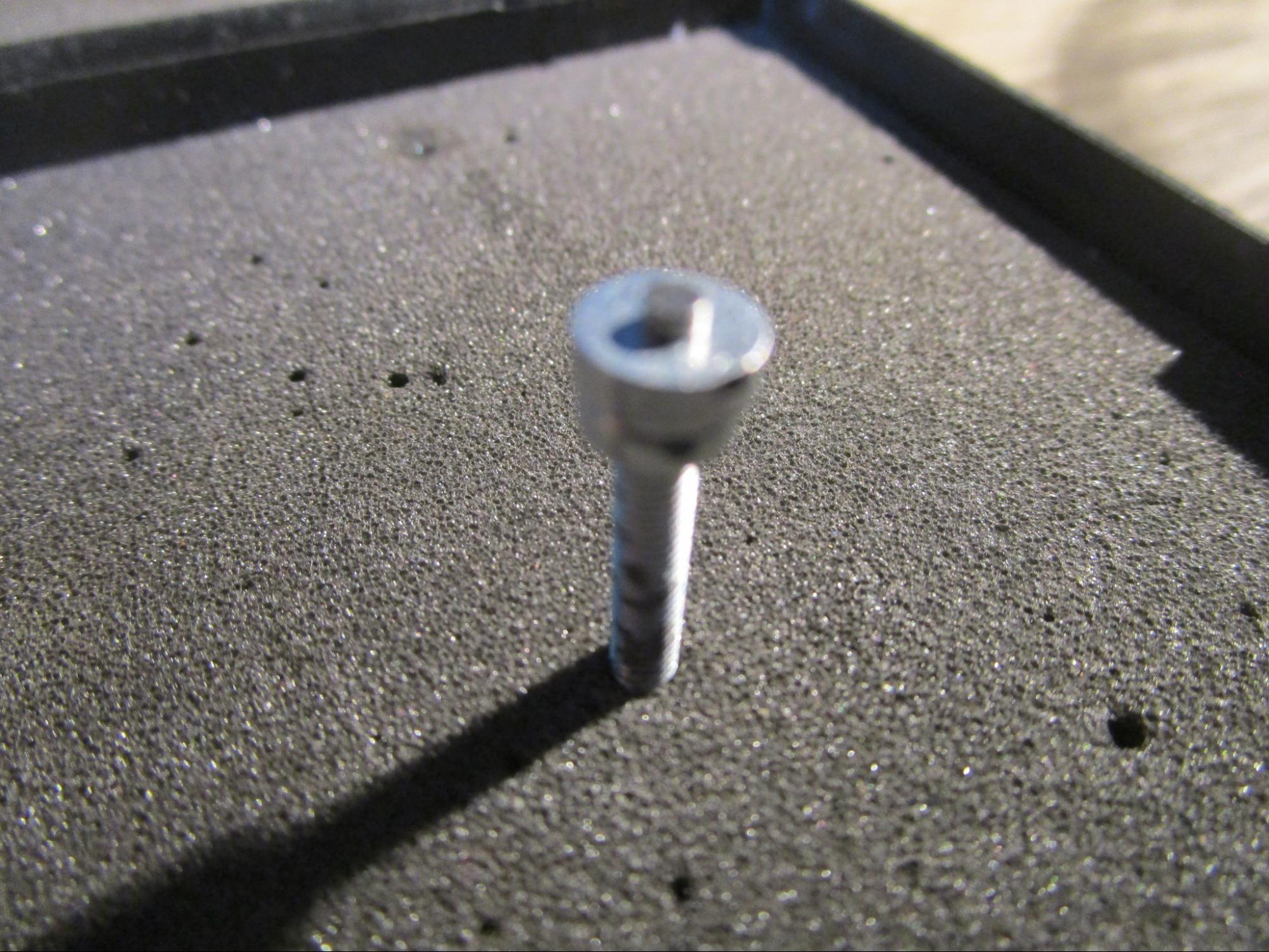
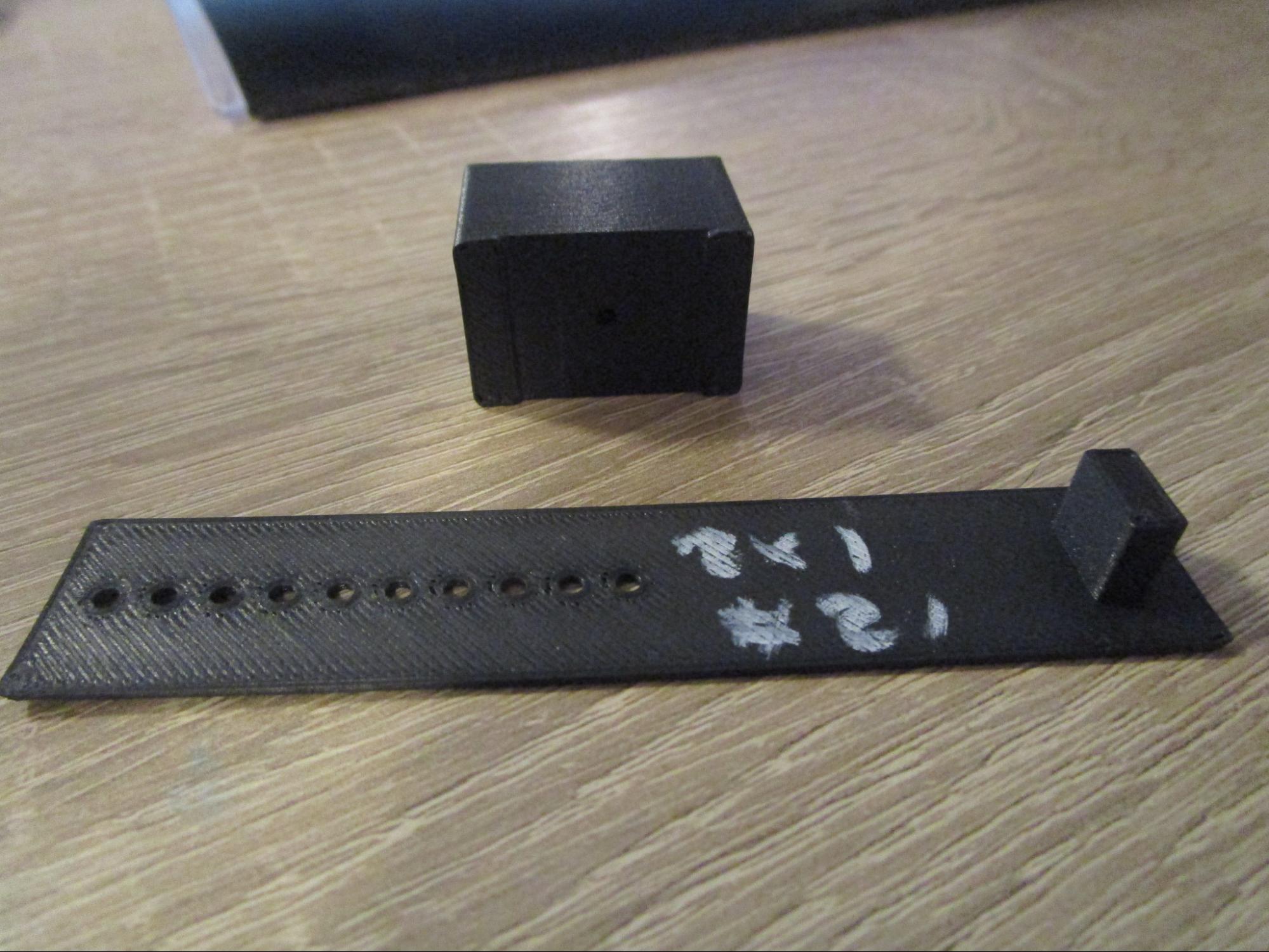
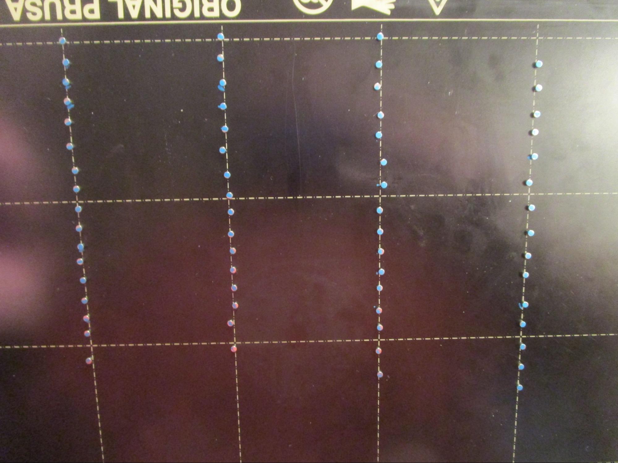
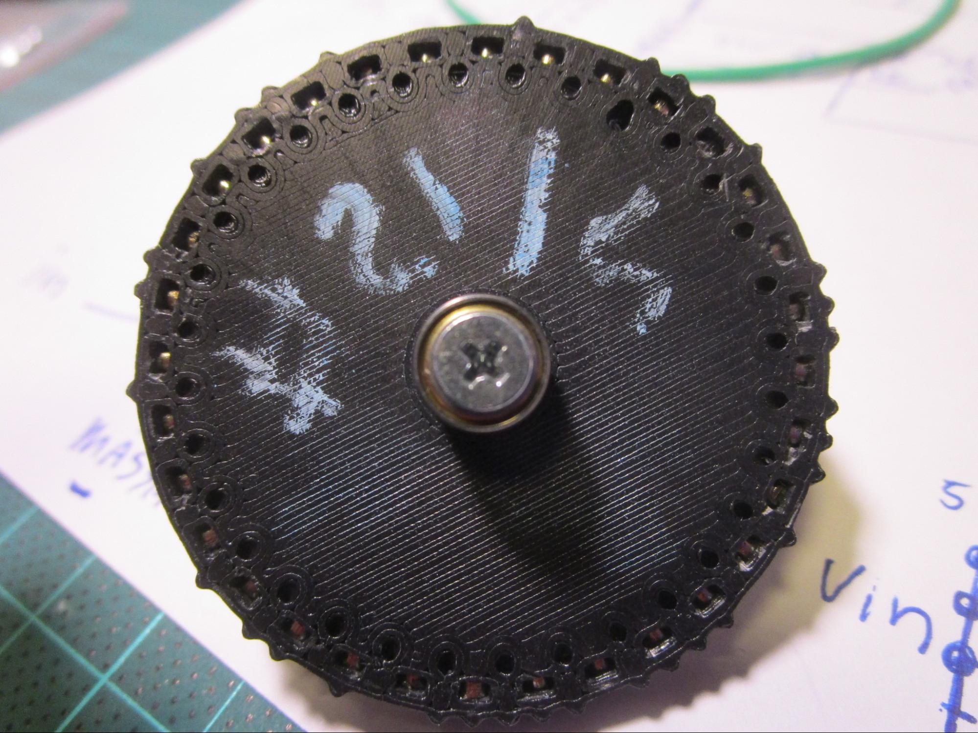
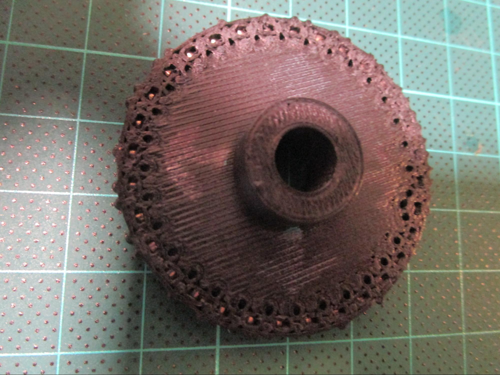
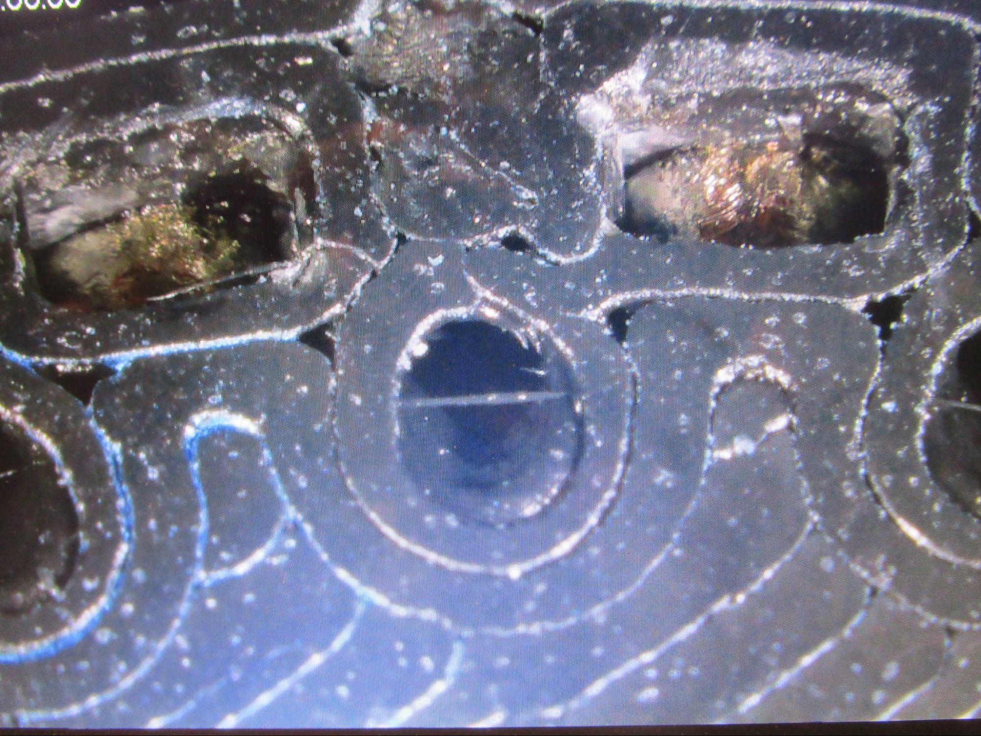
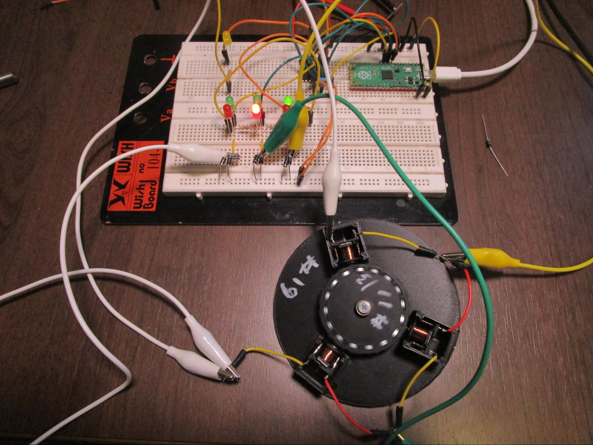
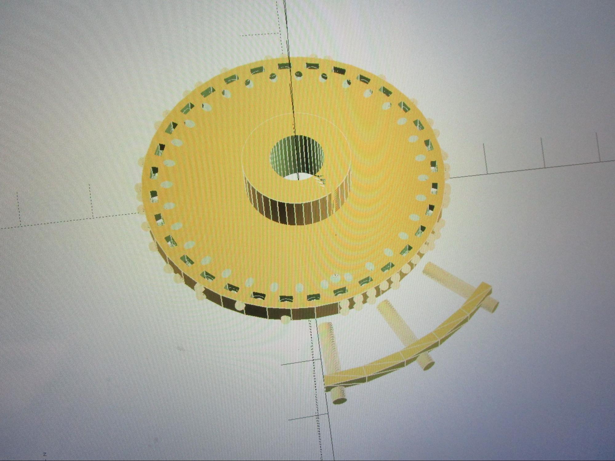
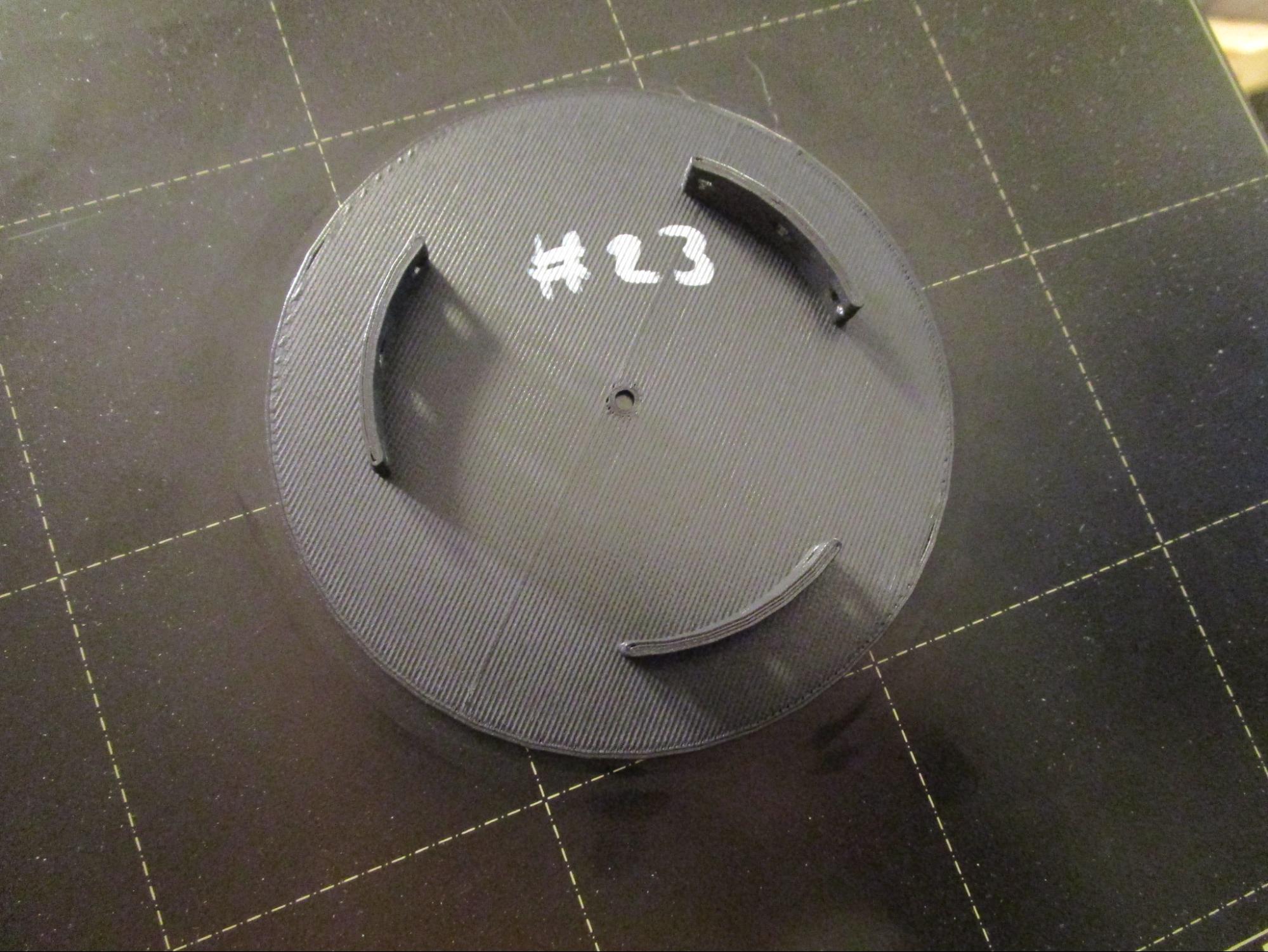
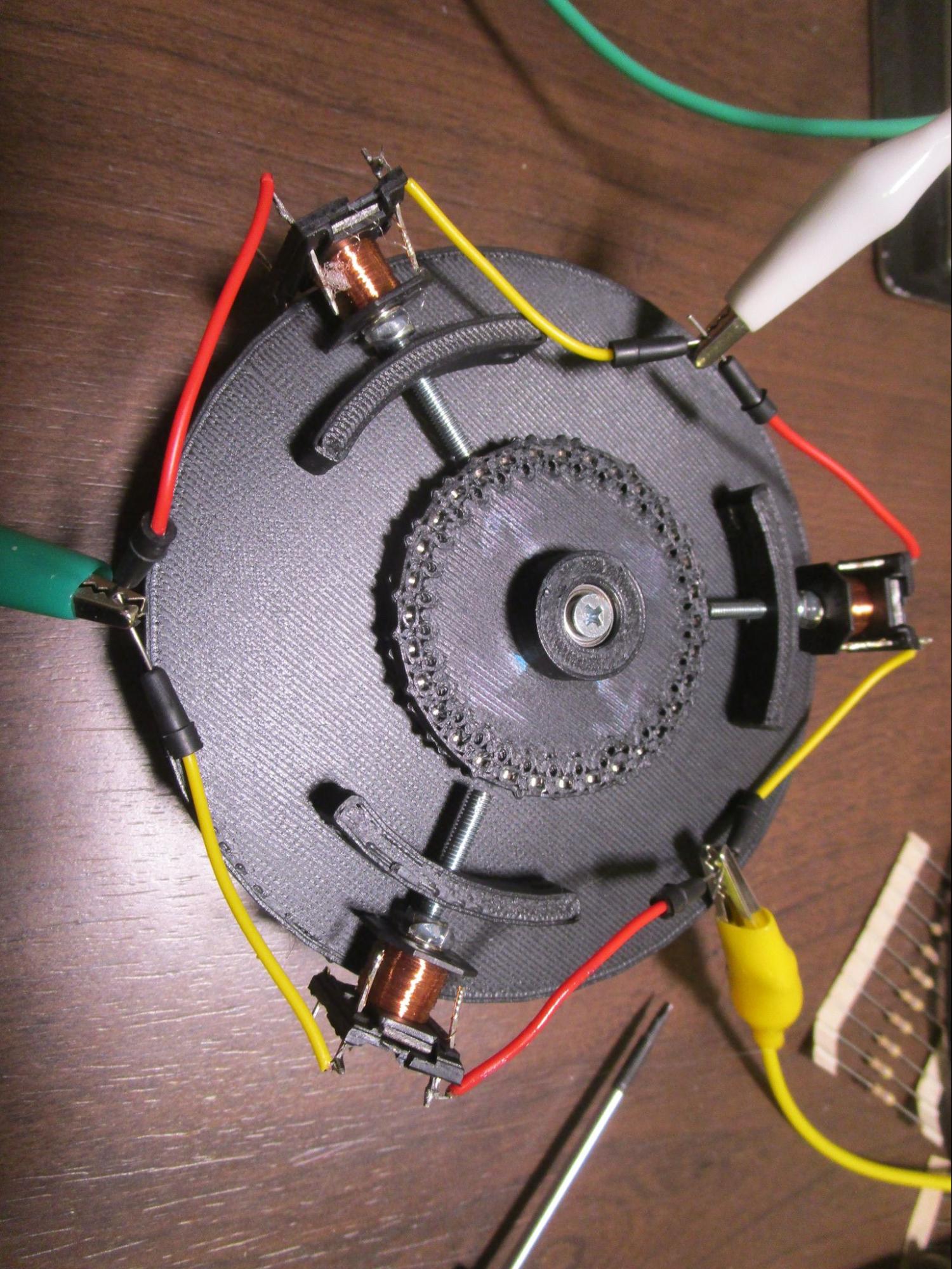
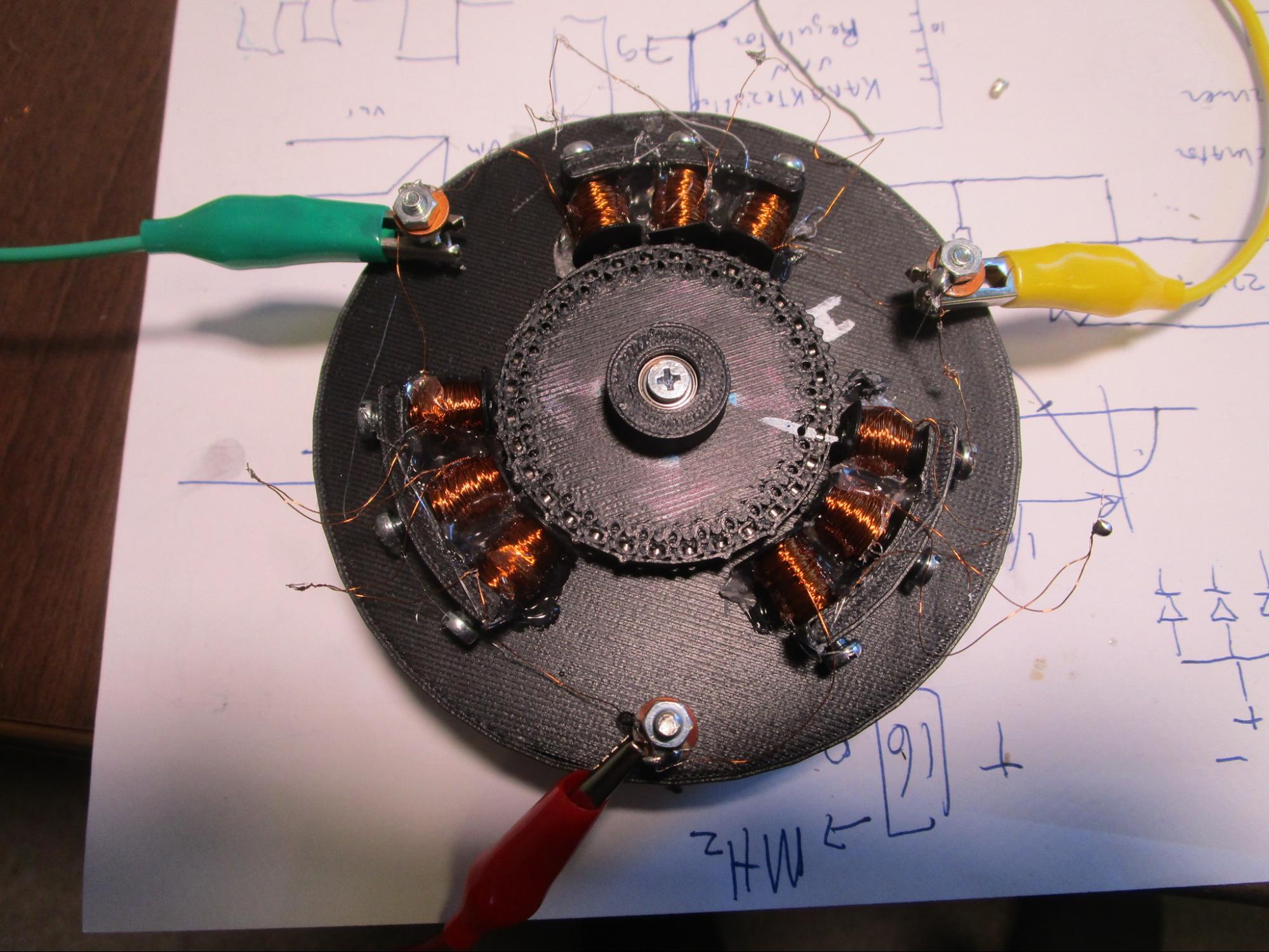
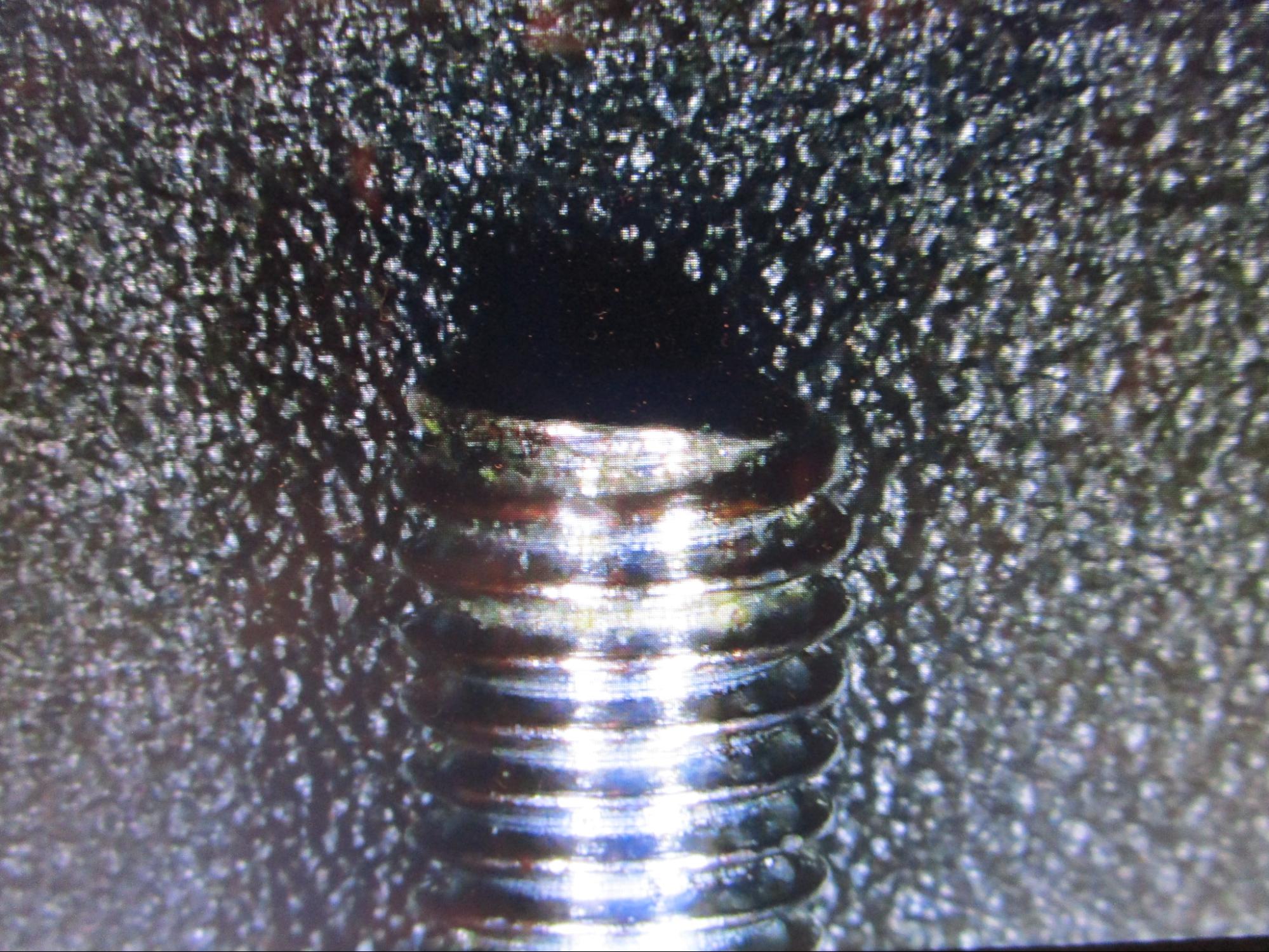
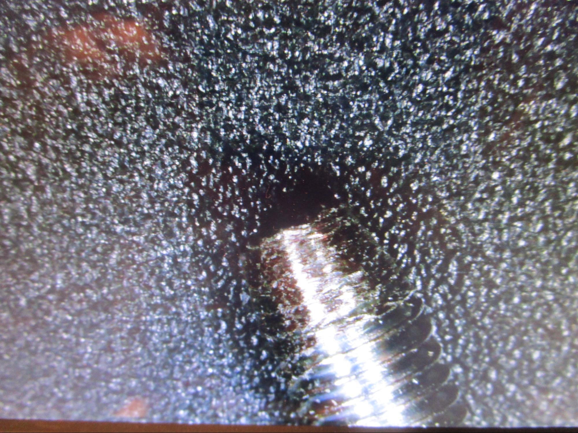
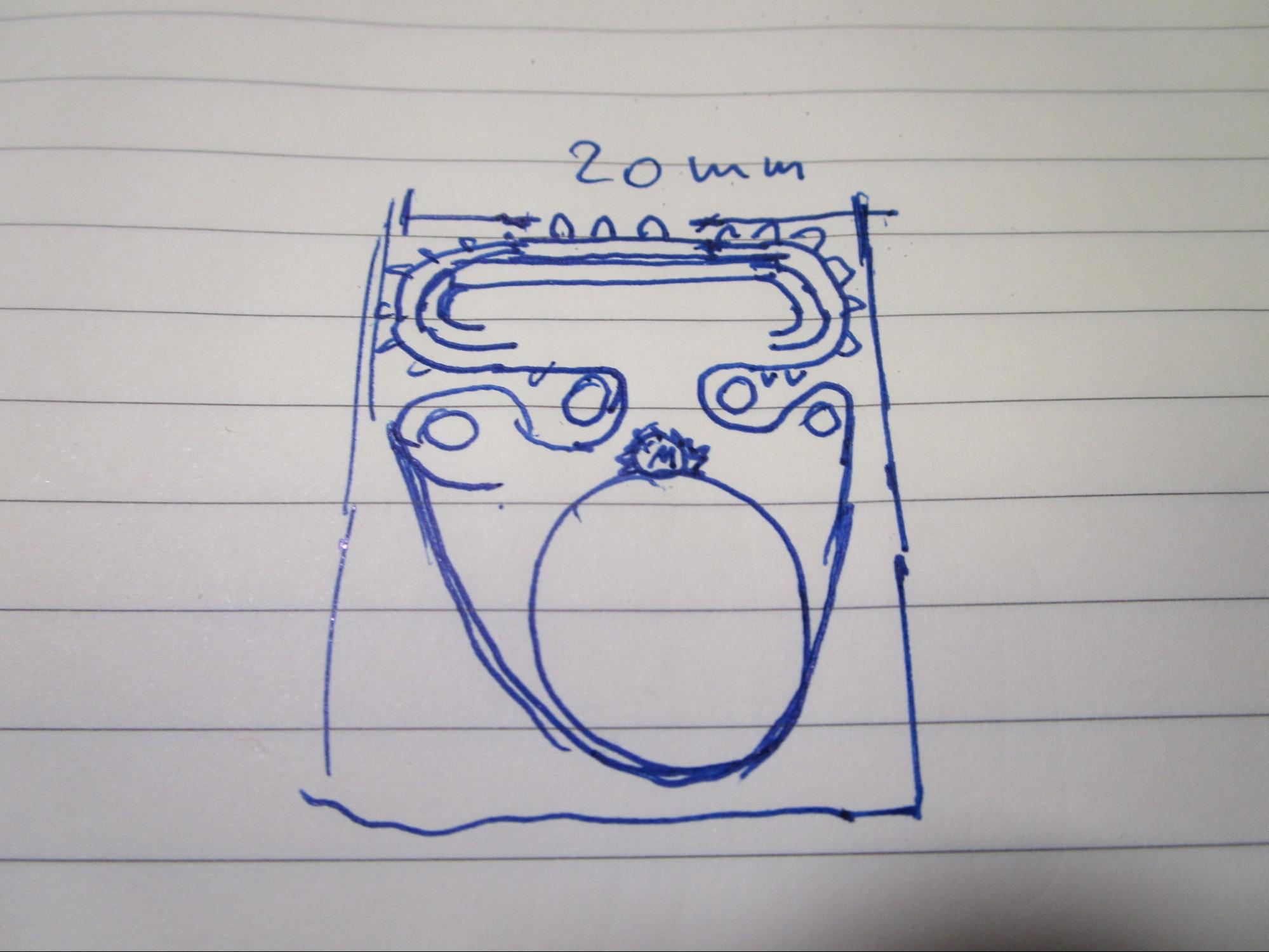
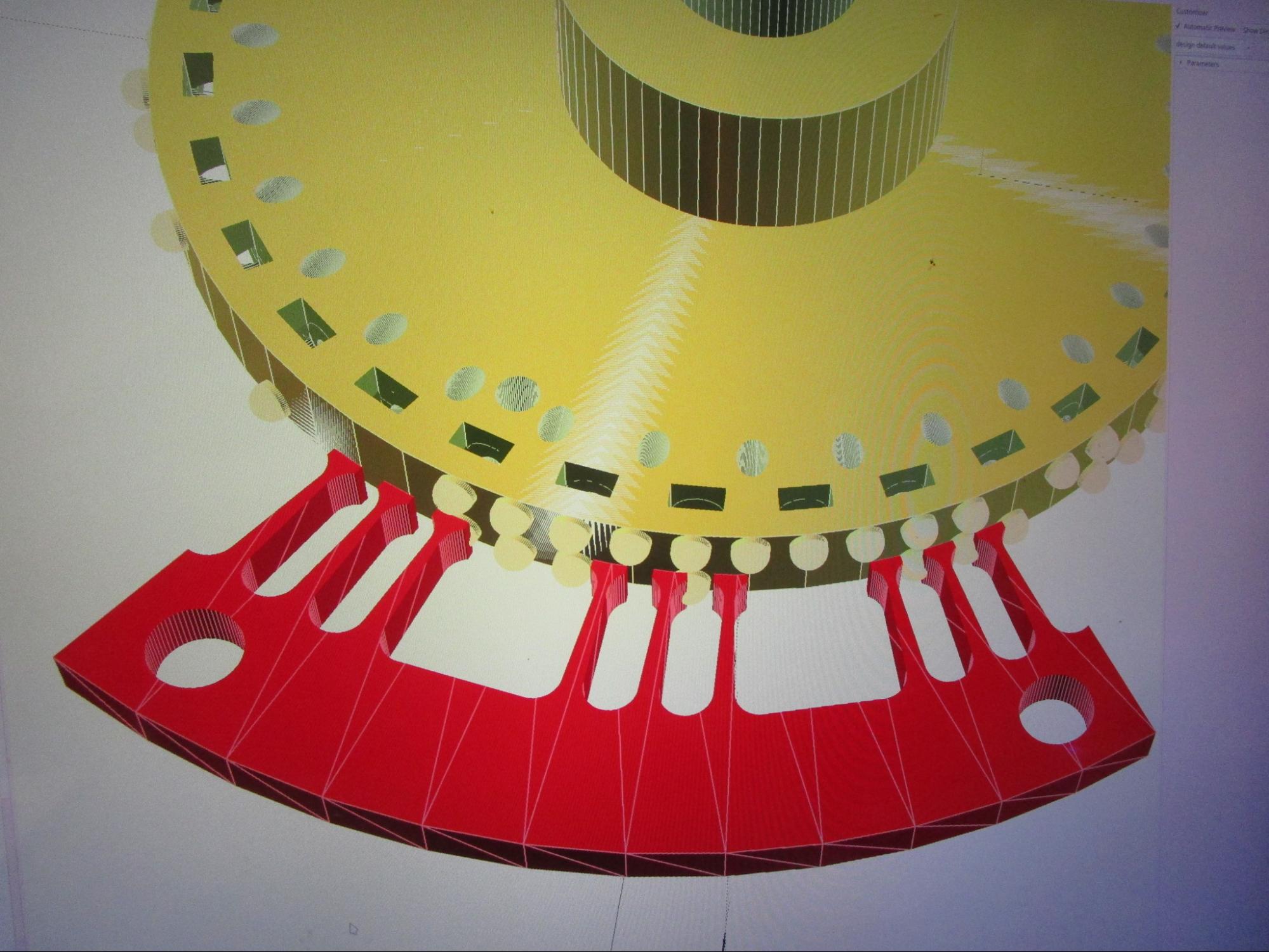
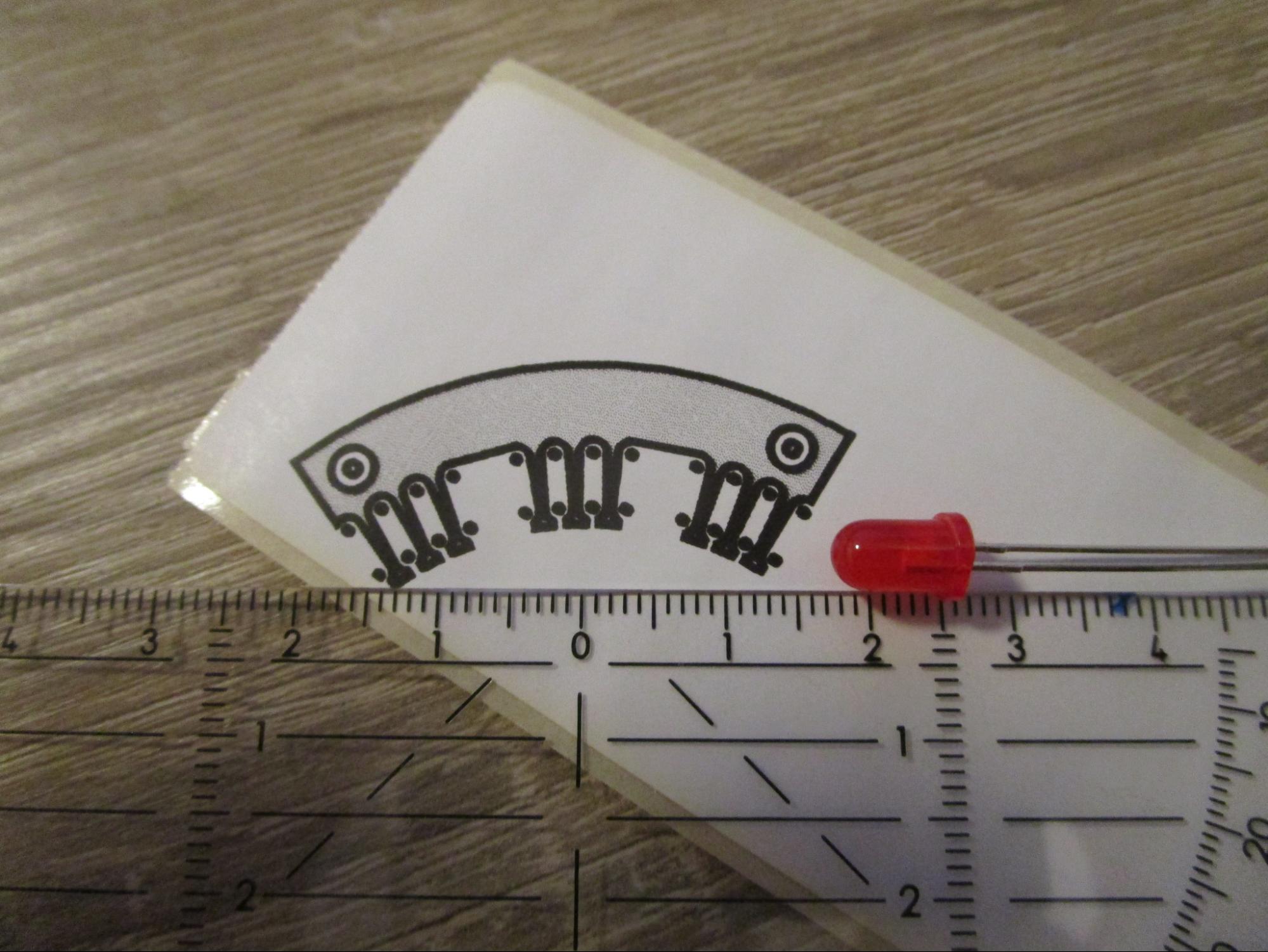
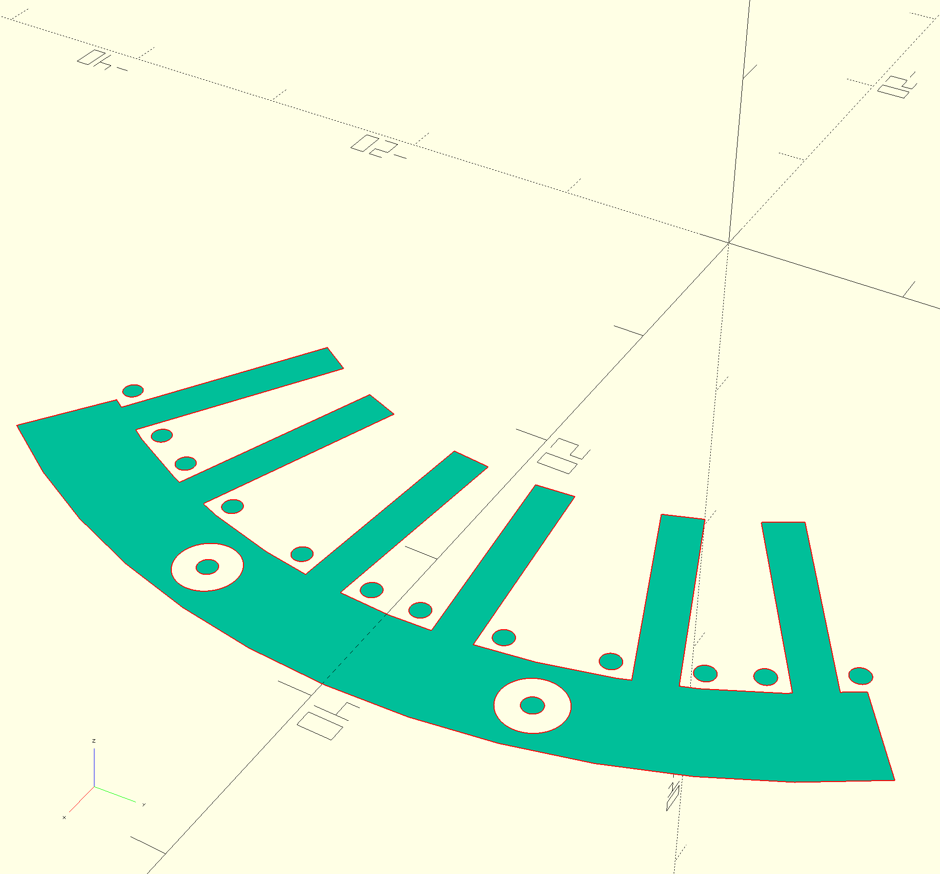
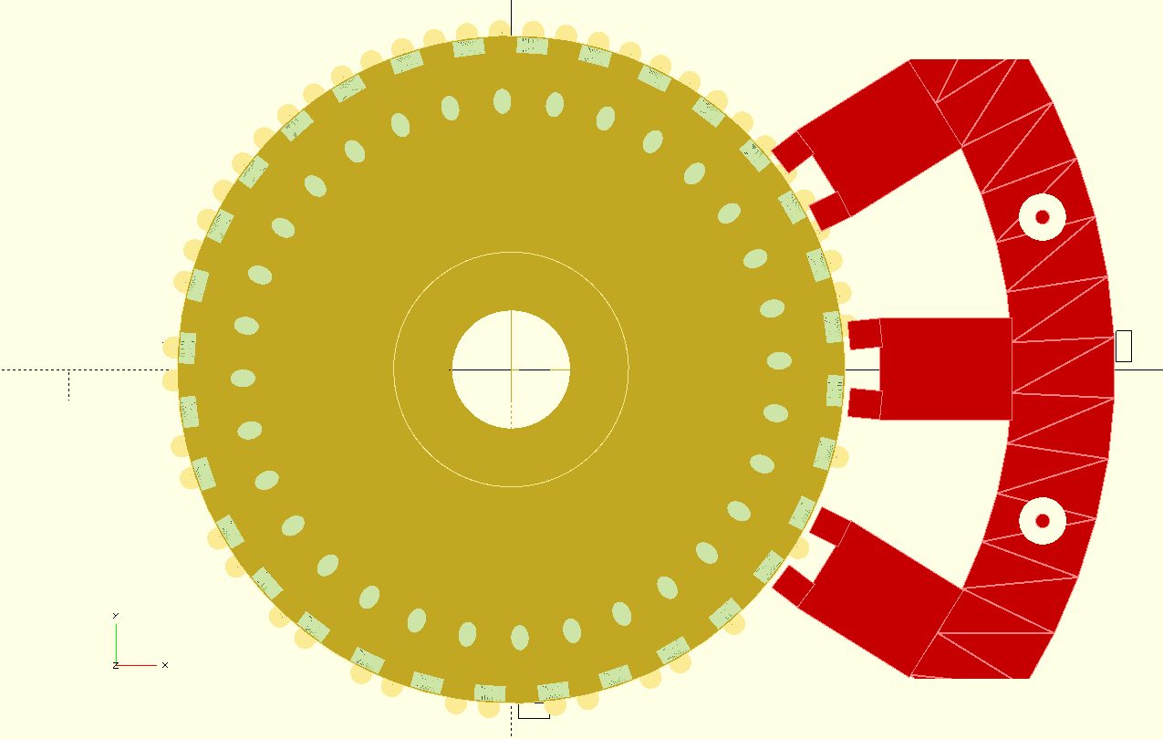
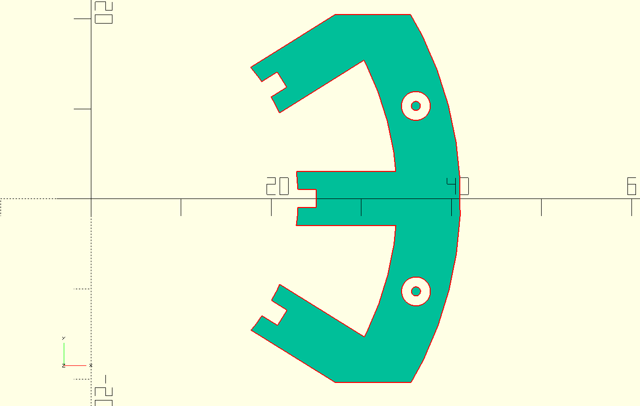
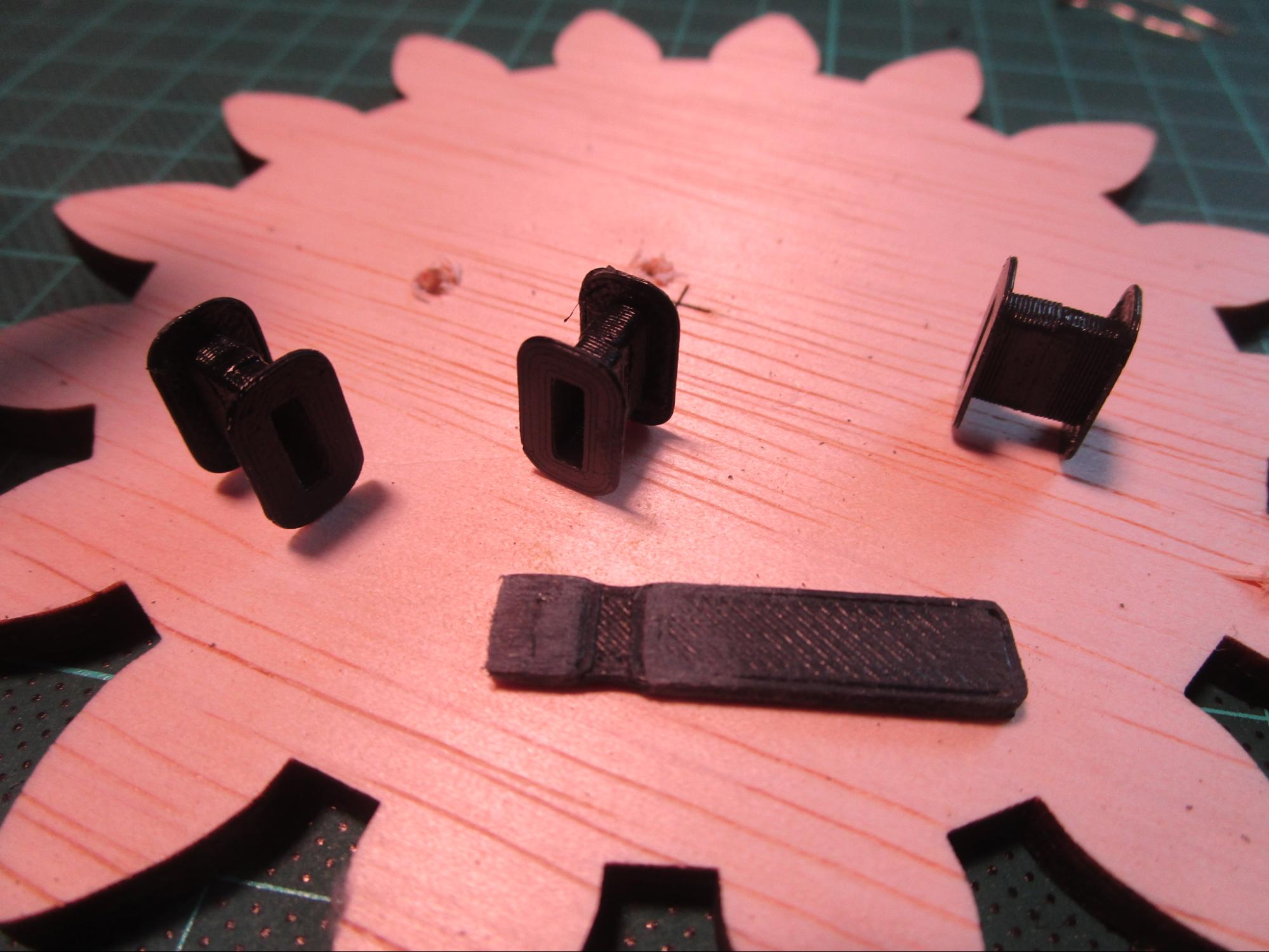
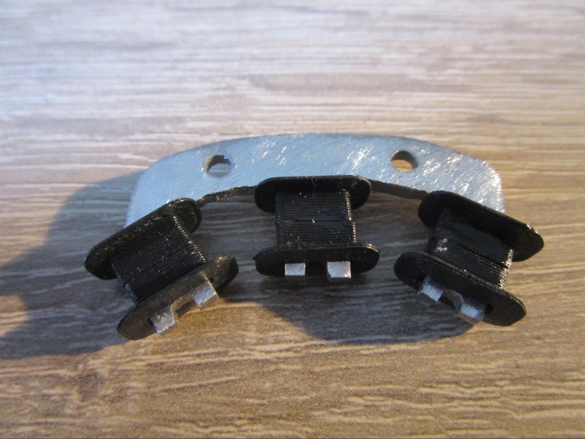
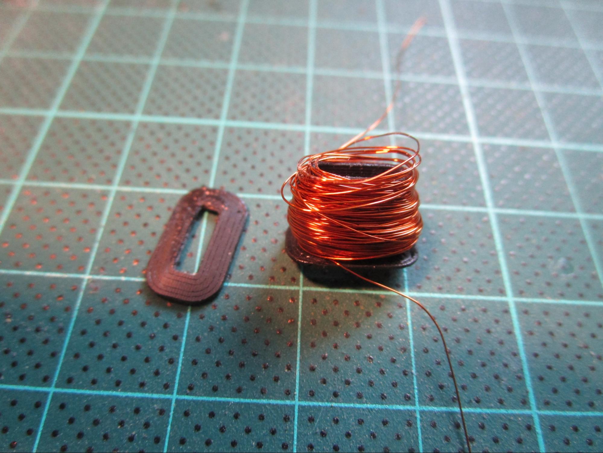
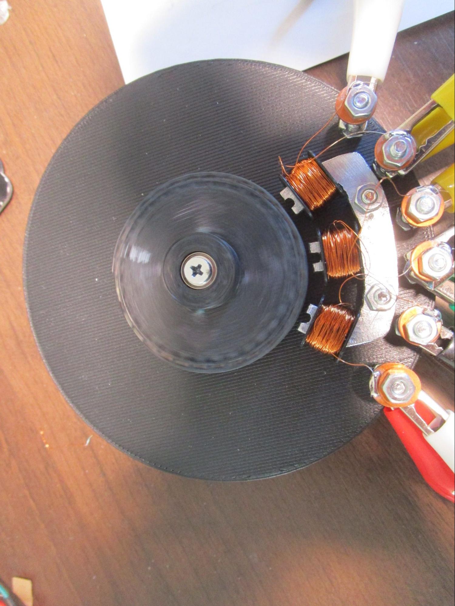
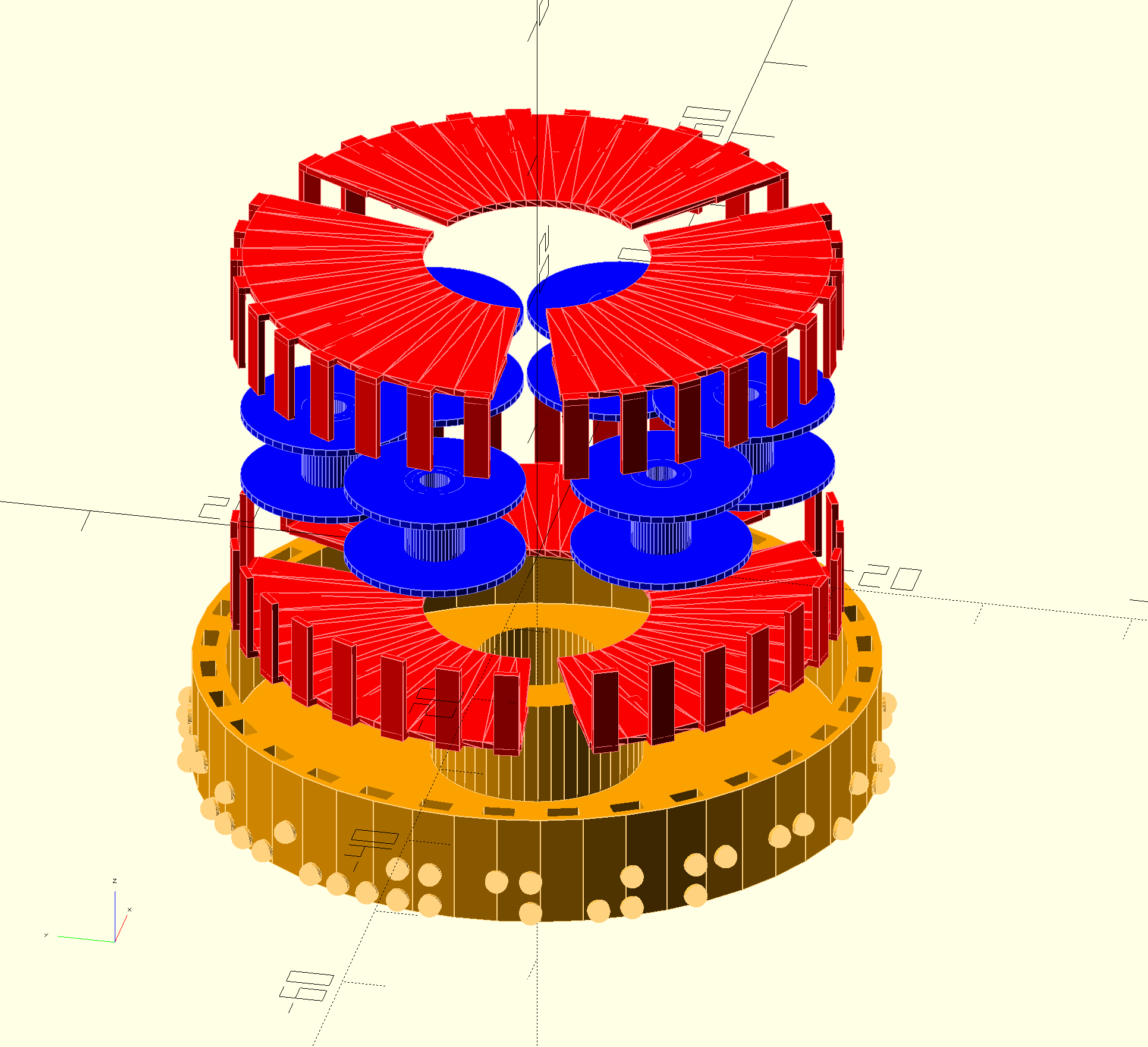
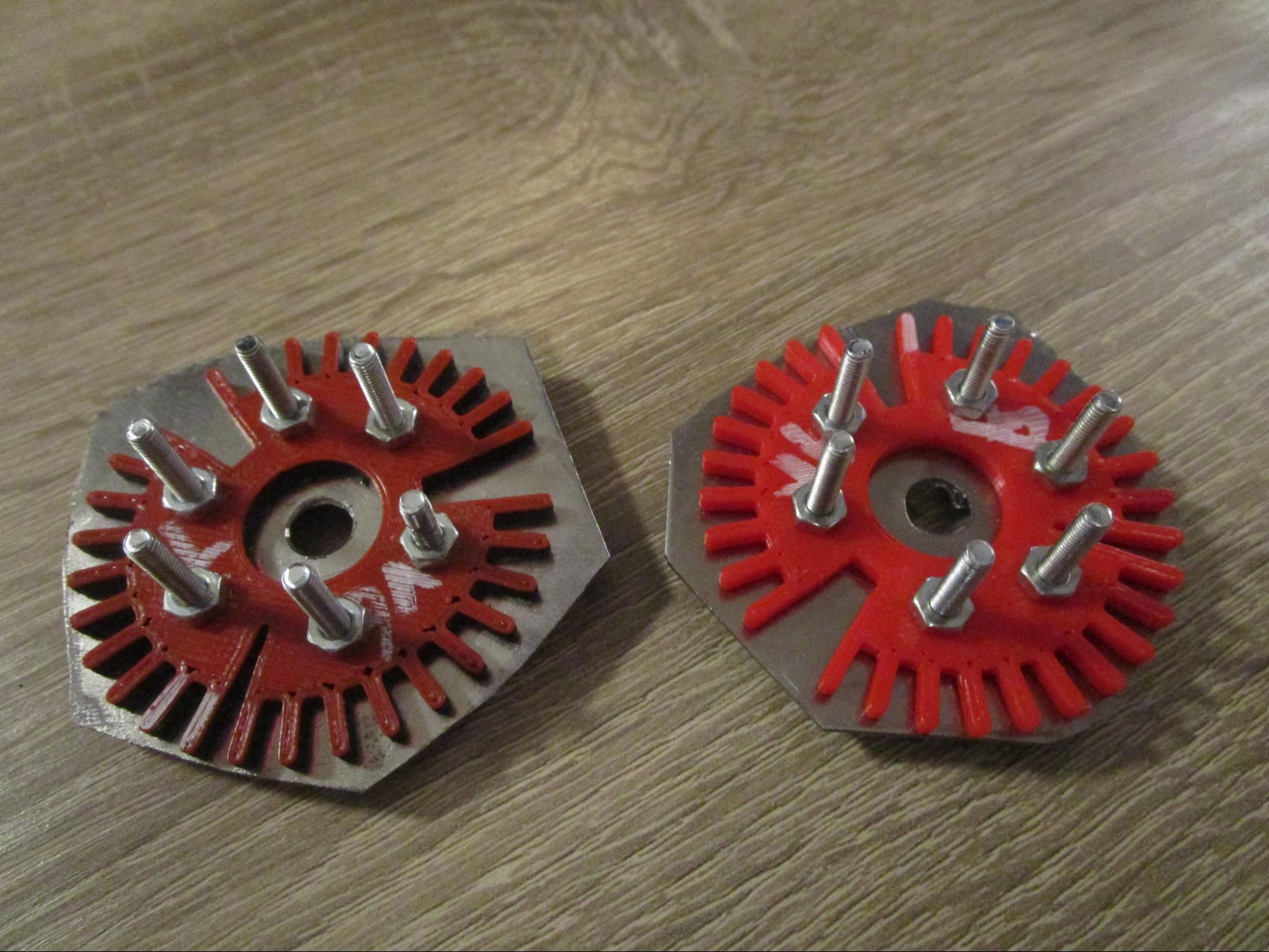
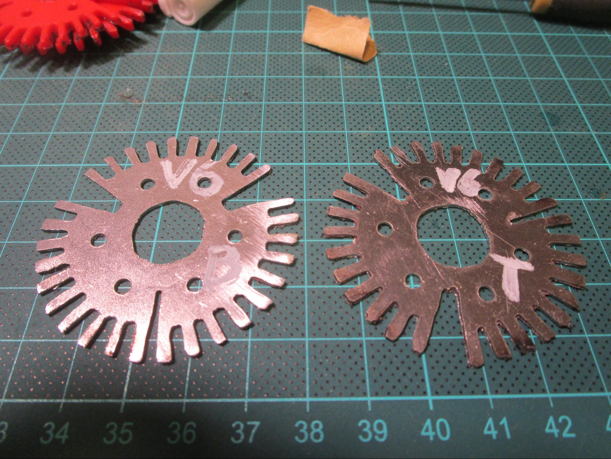
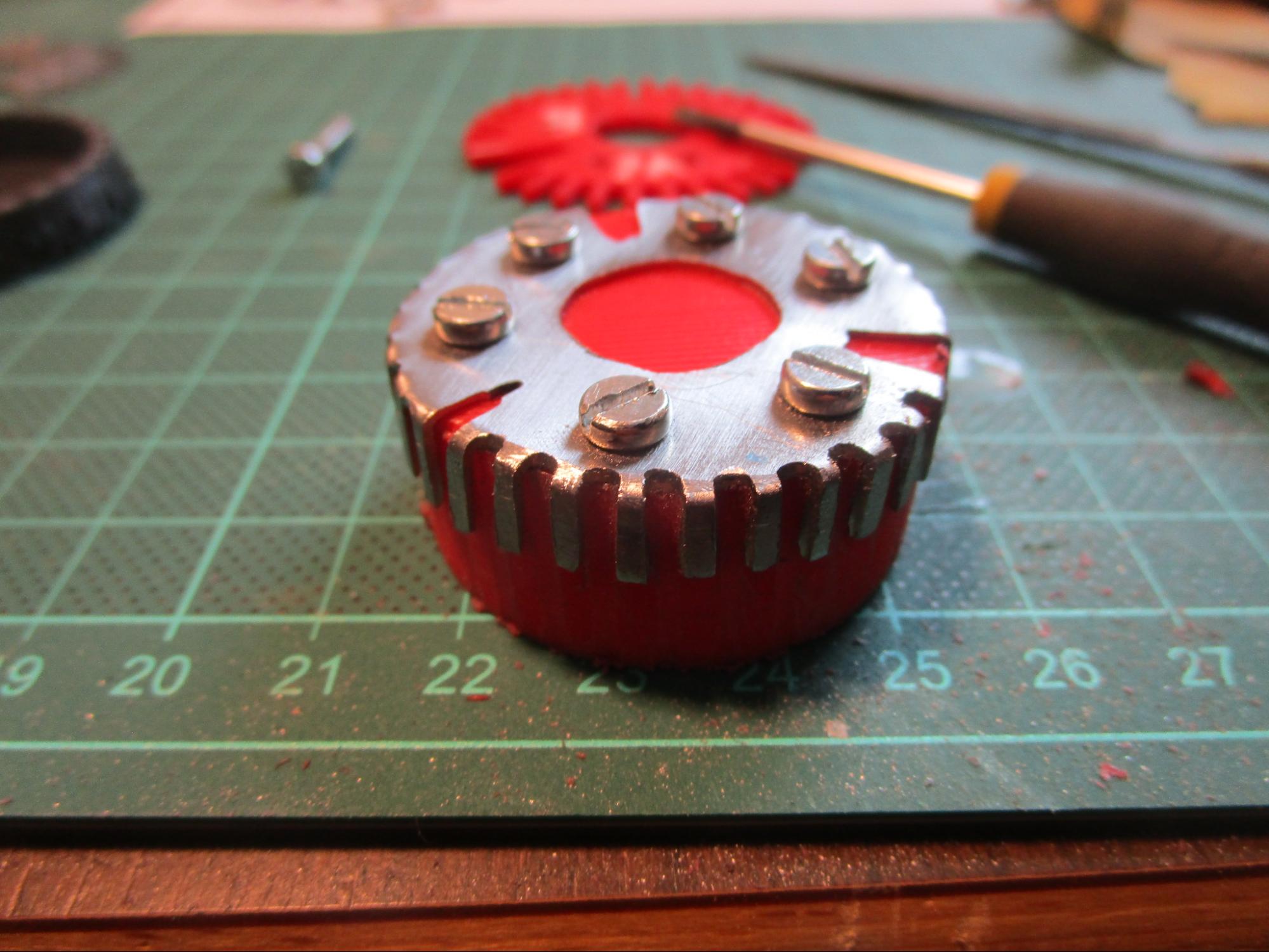
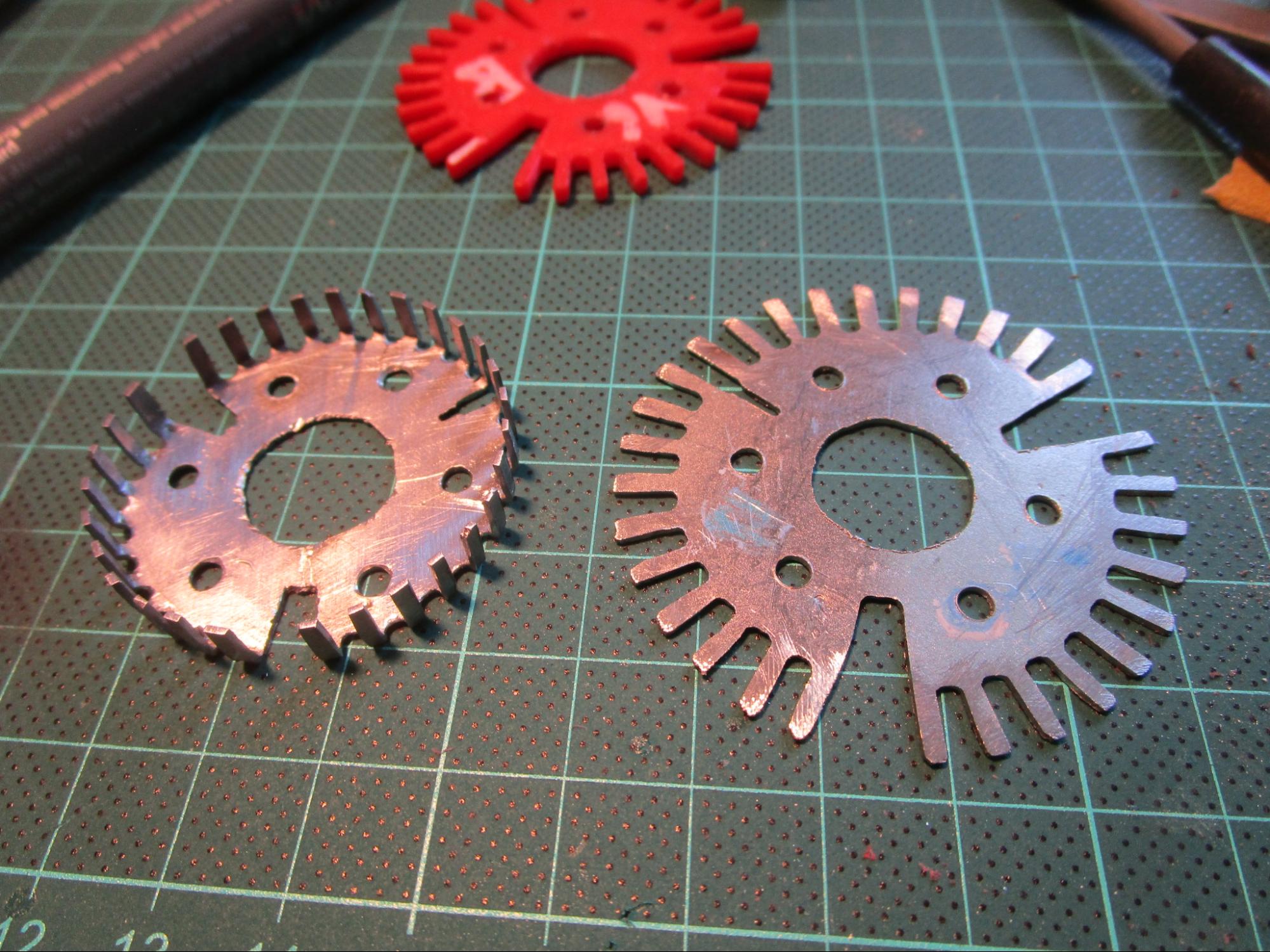
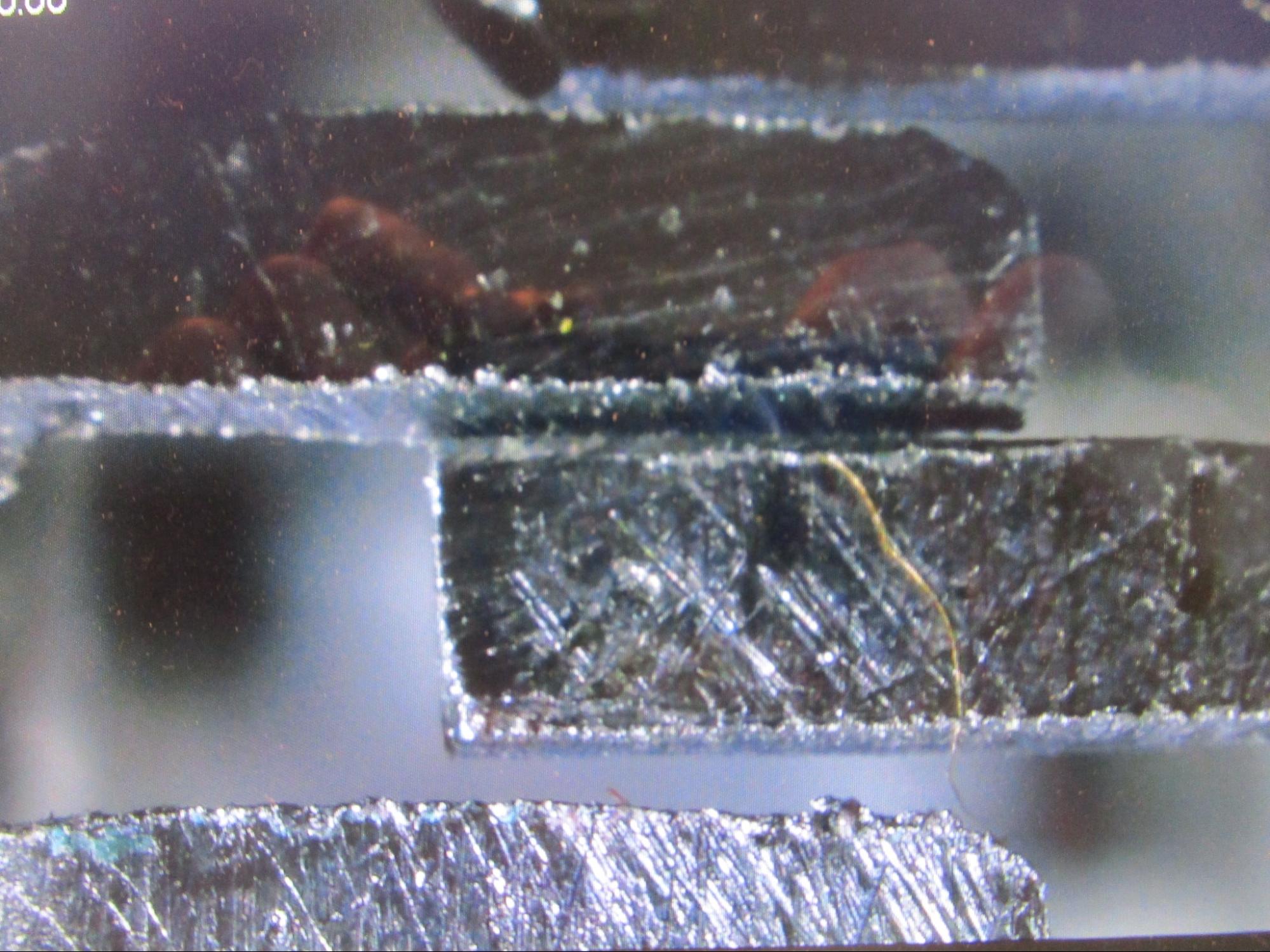
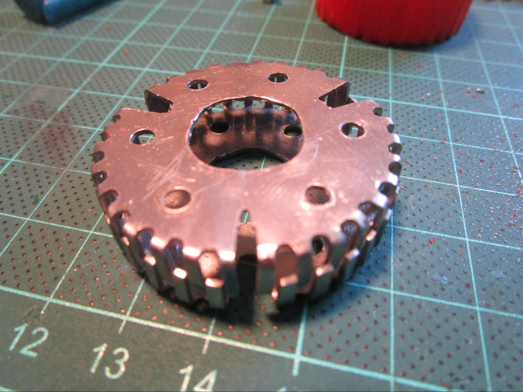
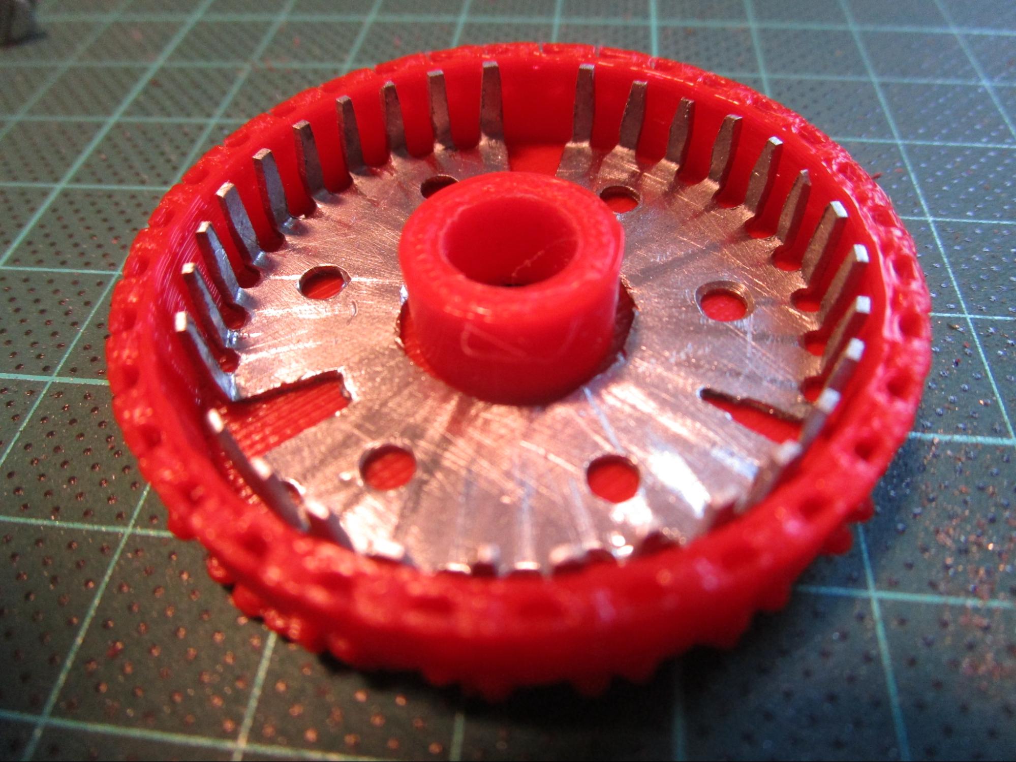
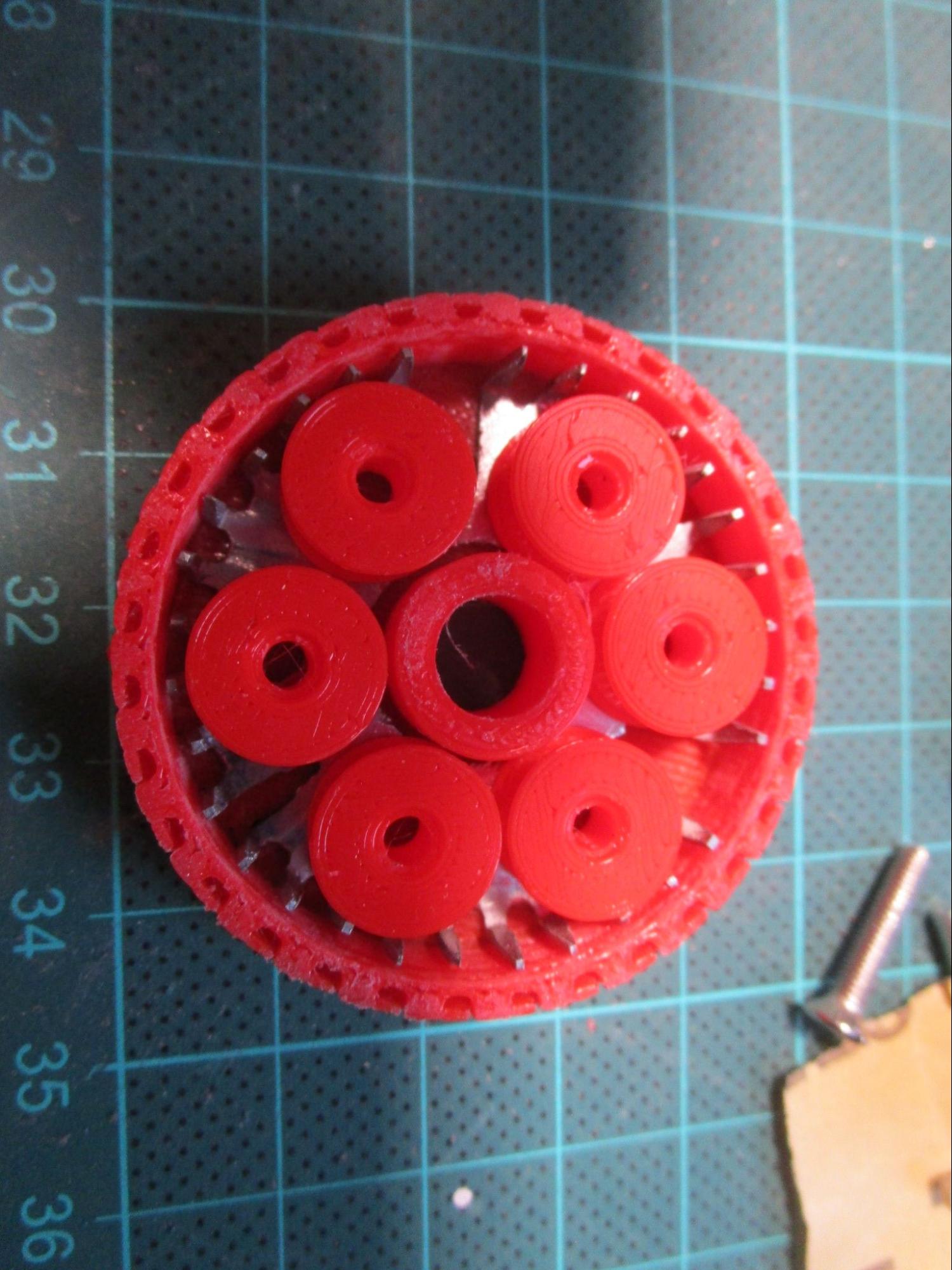
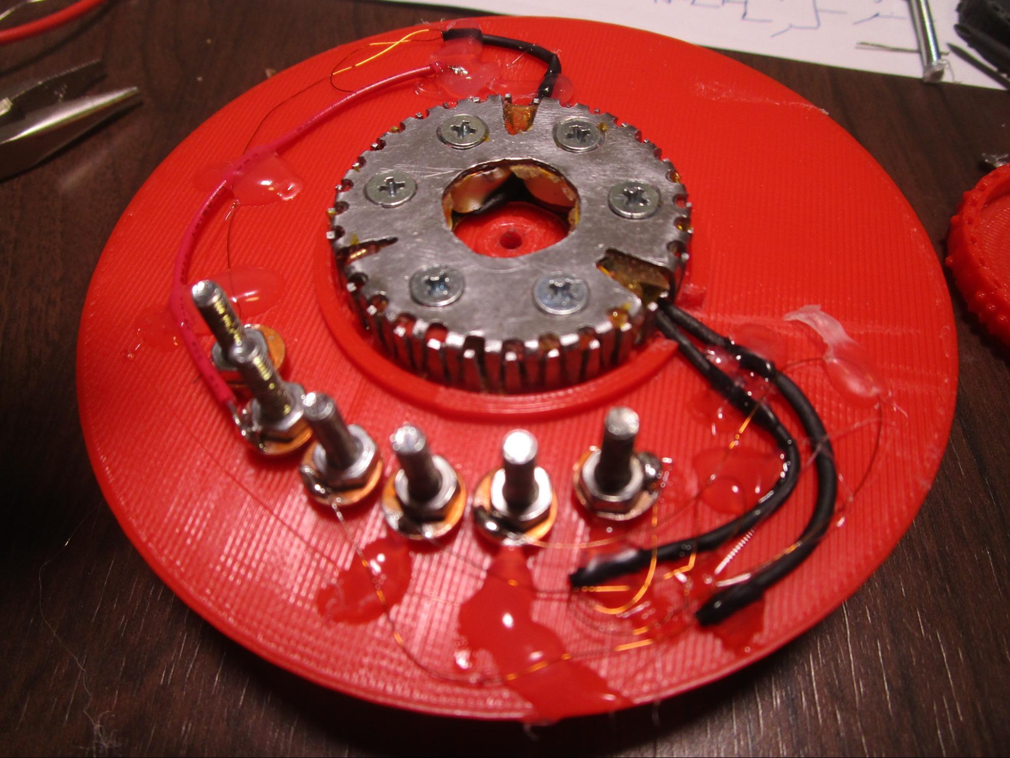
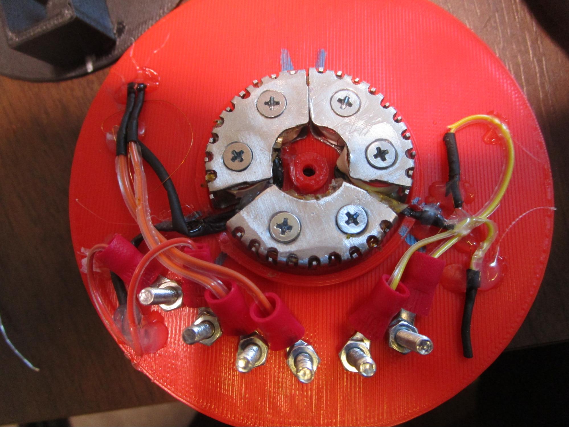
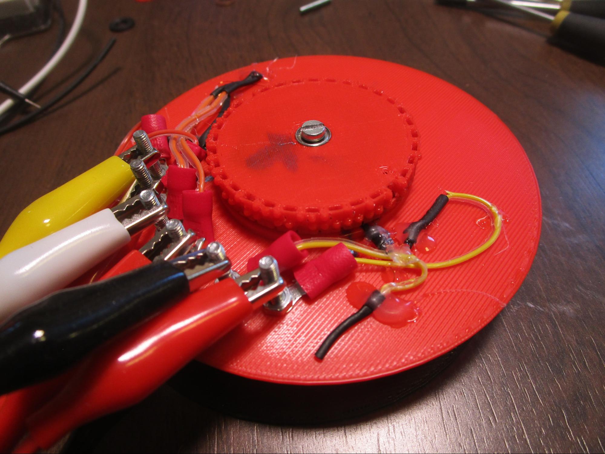