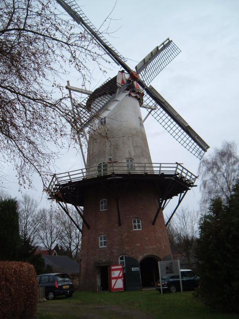
 Windmills have always fascinated me and for a long time I was dreaming of one day building my own. Where I live there are still machines from the 1600’s that are just as magnificent today as when they were first built. When you see one standing in a field rotating and converting passing air into usable energy they look like simplicity incarnate, but nothing could be further from the truth.
They’re complicated beasts even the most humble water pumper or a decorative item in someone’s garden. As soon as it is allowed to rotate freely driven by the wind there are a lot of things that you should take into account. And if you don’t one day you’ll wake up to find bits and pieces all over your yard, or worse.
The reason for this lies in the nature of the wind. That gentle breeze cooling you down on a summer morning and a gale 10 force flattening trees and ripping up buildings are only separated from each other by a single metric, the wind speed. The amount of energy that passes through a given area goes up as the cube of the speed(*). So a windmill that is spinning happily at its designed windspeed of 10 meters per second will have to survive in an environment where the amount of energy put into the system is a very large multiple of the energy at the designed (or ‘rated’) speed. That is a very difficult engineering challenge to overcome.
There are a number of strategies for mitigating this problem: shutting the windmill down (which requires a reliable mechanism to do so) above the rated speed or gradually reducing the fraction of energy that the windmill extracts from the wind.
Even the shutdown concept, which seems to be at first glance the safest approach is quite a challenge. Once a windmill is moving shutting it down is not something that is going to work unless you’ve really thought the problem through. Mechanical brakes have been used since the dawn of windmill construction, and they’ve caused many a windmill to burn to bits before the wind could rip them apart. Typically they work best when the windmill isn’t moving yet but the usual time when you find out that you want to shut down is when the machine is already working. Friction + a ton of energy = lots of heat. If the heat has nowhere to go the machine will at some point ignite the grease in the bearings or it will simply function as a very large scale fire bow. The end result is as predictable as it is sad.
So enterprising engineers figured out other ways to deal with this seemingly simple problem. Some involve designs that will move the windmill at an angle to the wind reducing the effectiveness of the blades. Figure the surprise on their faces when they realized that a windmill once it is spinning has two stable attitudes if you discount the tail, sideways into the wind where it will slow down and head on where it will speed up until it blows apart. So that trick does not work very well with windmills that can seek their own direction. Lots of methods to do this have been tried, many of them are usable to some extent (furling as this technique is called can also be done along other axis, for instance upwards). Others concentrate on the blades themselves, changing the angle of attack so the blades will not be as effective as they are below the rated speed. This latter method is known as pitch control and it is one of the most complicated but also one of the most effective and reliable ways of dealing with overspeeding.
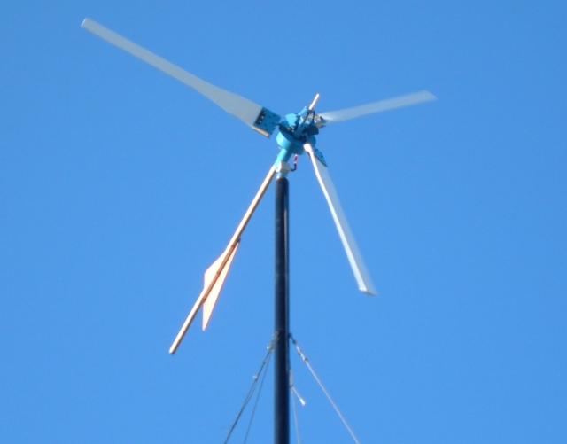
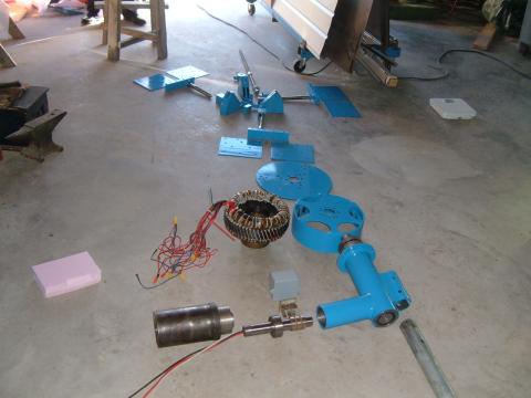 The design parameters of my homebrew windmill are: 2.5 KW of output at a windspeed of 10 m/s, variable pitch blades, rotor diameter 5 meters (about 16’). The total weight of the machine is about 85 kilograms (or about 170 pounds). It has survived numerous storms and worked very well supplying our house with reliable power, far more reliable than the solar panels we had used exclusively up to the point the windmill was finished. The plan was to open-source the design and to make available a list of parts. I really should get around to that one of these days, the fact that I finally had the time to do this write up means that there is hope ;) If you bought a machine with those specs commercially it would have cost about $10,000, but that would not be a variable pitch one. This machine cost a (fairly) large multiple of that, not counting our time, tooling and so on, but it could be reproduced well under that $10,000 mark if you already had all the tools and the knowledge and you didn’t have to go through a prototyping stage. Prototyping is very expensive and time consuming.
Designing a machine that size was a lot harder than I ever thought it would be. What was intended to be a one summer project turned into a two year tour of technology including magnetic theory, power generation, mathematics, mechanical engineering, woodworking, metalworking, meteorology, CAD/CAM, computer programming, electronics and aerodynamic theory. If you feel like acquiring some real world skills, go build a windmill! I never ever realized how much knowledge goes into making one of these until I tried it for myself.
The most demanding bit in my spec was that the windmill should be super reliable and should not require maintenance other than a lube job once every year or so. The place where it was put up has some of the harshest climate conditions on the planet, winters with days of -40 celsius and summers of +35 and sometimes even higher. Taking the windmill down during the winter was absolutely not an option (too much snow and no grip for the tractor used to raise and lower it) so reliability was extremely important, being without power would mean that our house would become un-inhabitable almost instantly (no backup power grid, we did have a stand-by diesel generator which was used quite a bit before the windmill was installed).
When starting out I thought this was going to be a one-man job. I did not intend to involve as many people as it eventually took and I’m really grateful to all the people that lent a hand (or two) at fulfilling my dream and that helped with their knowledge, skills and time. Without that it would have never ever worked.
Windmills consist of several major components: a structure that holds the generator, typically a tower of some sort, an alternator, an optional gearbox (the one described here is direct drive so there is no gearbox), a rotor plate + (optional) governor that holds the blade assembly and the blades themselves, and finally a tail.
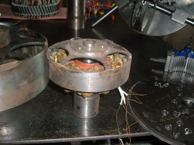 To learn more about how windmills work I decided to build a 1⁄2 scale model first. It probably doesn’t seem like a big difference, 15 cm (about 6”) or 30 cm (about 12”) for the rotor drum that holds the magnets but the scale model you can pick up with one hand whereas the ‘real’ thing (the scale model is just as real, it is a functioning machine) takes two adults to lift it. The idea here was that all or most of the trouble that would be experienced in the large machine would be present in a smaller one, where mistakes would be cheaper and easier to fix.
The first problem we hit when building the scale model was that even though the machine was quite simple and small, the precision required to make the pieces was well beyond what I could do with the hand tools that I had available when I started this project. Bit by bit we assembled a pretty formidable array of metalworking tools. In the 80’s I’d co-founded a CAD/CAM start-up which had taught me a lot of metalworking skills and those came in pretty handy. We bought a lathe and a mill and used these to make the drum and various other componenents of the scale model. Of course I could have outsourced the work but I really wanted to do this myself. What use are skills if you can’t use them :)?
We hit a serious roadblock when we came to manufacturing the stator, the part of the alternator that holds the coils used to generate the electric current. The difficulty was that the design called for an ‘inside out’ stator. The reason why is that I’d observed a tendency in windmills run by members of the same forum that I was active on at the time tended to spit out magnets leading to catastrophic failure. By inverting the design, putting the rotor on the outside as a drum instead of on the inside the force on the magnets would simply push them harder against the drum they were placed in, instead of attempting to eject them from a spinning core where they were on the outside. At first sight that was a no-brainer, but making an inside-out stator was a lot harder than using any one of a 100 different models used in the industry where the coils are on the inside (almost any electric motor has that arrangement) of the laminations. So we ended up having to manufacture our own stator elements.
The stator consists of a stack of thin metal sheets, each insulated from the other to reduce an effect known as eddy currents. Eddy currents are bad for two reasons, the first is that they cause the windmill to be less efficient, the second is that they tend to warm up the stator and that can lead to failure of the whole machine if it gets out of control. Coil losses are bad enough to contend with.
Each stator sheet is a circle with some mounting holes on the inside, and then a bunch of ‘fingers’ radiating outward and little edges attached to the fingers to hold the coils. Imagine a dinner plate with capital ’T’ letters tacked on to the edge radiating outward. Drawing that in the cad tool was really easy, but realizing the drawing in metal turned out to be very hard indeed.
At this point we took a 6 month detour in the wonderful world of sheetmetal fabrication. This was a lot harder than it seemed at first. Finally we settled on using a plasma cutter to cut the stator elements from standard sized sheets of metal (a special kind, which is low on carbon and has very good electromagnetic properties). Die cutting was impossible due to the cost of the dies, but if this were ever produced in volume that would be the way to go).
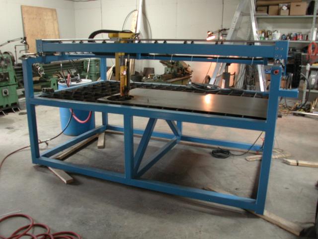 A rig was built to hold the plasma cutting head and a sheet of metal, the whole thing operated by stepper motors connected to a small computer that ran some homebrew controller software to translate the design (made using ‘qcad’) into metal pieces. Building that machine and getting it to work properly was a fairly big project all by itself, in many ways more complicated than building the windmill! One interesting sub-problem was that to make the plasma-cutter gantry we needed to have - you guessed it - a working plasmacutter. We solved this by hacking one out using the hand torch to bootstrap the machine, and then used that to make the real gantry.
Working thin sheets with a plasmacutter is very difficult. The first attempts failed horribly, the sheet would deform during the cutting causing the plasma cutter to come in contact with the sheet of metal (this is called a ‘strike’) which would short out the arc ruining the plasma tip (they’re consumables but they are not cheap) and this would cause terrible deformation. During cornering the cutting speed was too low which would cause the tops of the ’T’s to melt off because too much heat would be injected. Thin sheet is a very hard material to work using torches. Little by little we overcame these difficulties, the cutting speed by coming up with a way to make the stepper motors work much more smoothly (instead of ramping down to ‘0’ at right angles we ended up using very small arc segments or to purposefully overshoot the desired spot at speed and then to hit the 90 degree turn by making a 3⁄4 circle going the other way, which kept the cutting head moving at a nearly constant velocity, and any slowdown would occur in the scrap portion of the sheet).
To make the increase in speed possible the gantry was redesigned to be much lighter than the original which allowed for faster acceleration and deceleration which in turn made the cuttings much more regular and consistent. Originally the gantry system weighed about 80 Kg (about 160 pounds), the redesigned version weighed in at only 18 Kg (36 pounds). I came up with a funny way of using the cutter, I don’t think it was intended that way but it worked wonderfully. Instead of cutting all the way through some parts of the machine we’d simply score them, running at a speed much higher than the one required to make a full cut. This then leaves you with a nice ‘fold here’ line, after which you just fold them over and weld the edges up. You end up with all kinds of very rigid and precise box like structures like this. This technique was used to make the motor casings and the Z-axis support structure.
 Once we finally had the stator sheets ready they could be stacked and placed in the now nearly finished 1⁄2 scale alternator. During testing it produced about 500 Watts at 600 RPM, which was more than we had hoped for (the reason for this turned out to be that I had missed one elemment during the calculation of the the gap between the magnets and the rotor drum, I’d simply subtracted the magnet height from the rotor drum inner diameter but of course (well, in retrospect everything is obvious) the rotor isn’t flat but curved inward there, which caused the magnets to ride slightly higher and hence the airgap was smaller than it should have been resulting in an increase in output power).
With a working scale model of the alternator in our hands we began work on the larger version. The design was scaled up and we spent a few months on making all the parts for the real thing. All of the experience we gained making the scale model paid off and the 1:1 version of the alternator worked as designed the first time we tried it.
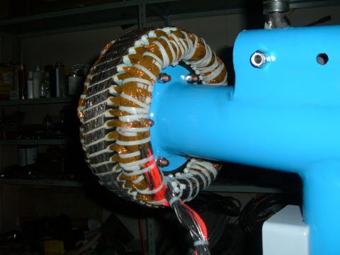 Here you can see the finished stator mounted on the base, the slant in the stator pack is to reduce ‘cogging’, the effect caused by the magnets lining up with the stator elements. If you don’t do anything about that the machine will vibrate terribly which will reduce the life-span and it will need a lot of wind to get going which means that you will be making substantially reduced power over a given amount of time. We used the big lathe as a test rig, the alternator fixed on the tool support and the lathe driving the rotor drum. We could easily stall out the lathe by loading up the alternator!
Next on the todo list was the rotor plate which would hold the blades and the bearings that allowed the blades to change pitch. The idea behind this rotor plate was a very simple one: each of the blades would be free to rotate around a pivot mounted on the rotor plate, the three blades would be kept synchronized by tying them all to a central ‘rider’ which would go up and down on a central shaft. Piece of cake ;). It took three tries to get this right, the pitch control mechanism worked by having a weight attached to the shaft for each blade, which was pushed out by the centrifugal force and a spring that pushed the rider back up. This gave a lof of adjustment options to change the dynamic response of the governor. Spring tension, starting angle, ending angle, pre-tension and an ending stop to limit the travel of the blades all controllable with two nuts riding up and down on the central shaft. In retrospect I would change one small detail here, I would add a hydraulic or air based shock absorber to reduce the speed with which the governor rider can move up and down the central shaft. That would have made the machine a bit more gentle in its responses to sudden wind speed changes. I never realized how quickly the wind can change direction or speed and the windmill would follow these changes almost instantaneously.
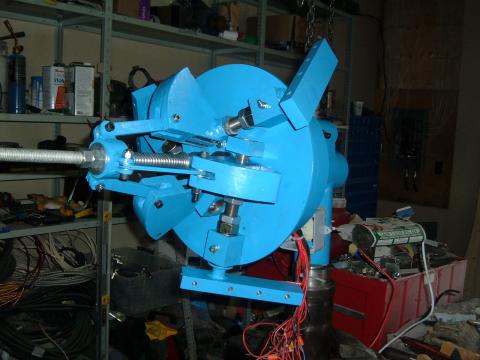 Even though this was time consuming and lots of solutions were tried and discarded this was by far the easiest portion of the whole prototyping process, the governor was tricky to figure out but relatively easy to manufacture. The weights in the picture as well as the base plate were cut out of 8 mm sheet steel (3⁄8”) using the plasma cutter. The weights are stacked segments that are then welded up and finished. This gives the same effect as a solid but is much easier and quicker to make than milling the same structure.
After the rotor plate and the governor mechanism were done we began work on the blades. Making three windmill blades that are identical in wood is hard. Wood, being a natural material is of variable density, and moisture will cause that density to change over time. Wood also doesn’t really like to keep its shape. After trying to make some blades by hand we settled on converting our trusty plasmacutter rig to become a 3D milling machine. The size was just about right so we could make a blade in two passes (one for the front, one for the back).
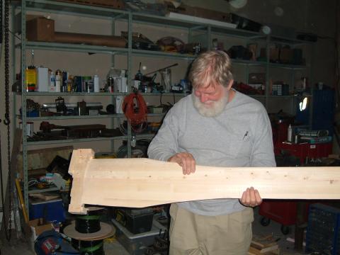 At this point I found that I had a friend in Texas who really liked the project and would mail me in the evening with the solutions for the problems we’d have the next day.
He kept on doing this and after a while I jokingly told him that if he really knows what we’ll be up against tomorrow, why not come over and give us a hand. And so he did! Enter Ron Brown, Texan, woodworker extraordinaire. Without Ron this whole project would have failed miserably at the ‘making the blades’ stage, the bit that we all thought would be the easiest part of the whole project.
Ron taught us a lot about wood, woodworking, making windmill blades in general and using a 3D gantry mill to make complicated objects with repeatable accuracy.
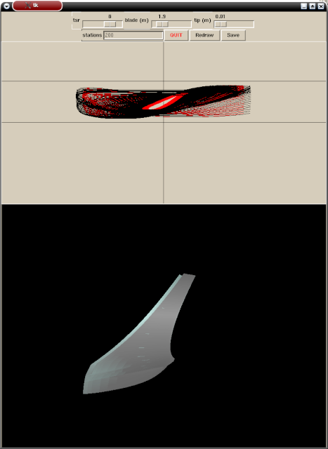
I wrote a small interactive python program to help with the design the 3D contours of the blade which then produced a file used by the program written earlier to control the gantry mill.
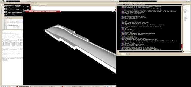
Trial runs in wood are expensive so I made a simulator of the 3D mill that showed on the computer screen what would have happened if we ran on the mill. This saved several forests. After we were confident we got the geometry right we prototyped a bunch of blades in foam and when we finally had ironed out the kinks and dealt with the challenges of ‘registration’ in a two sided piece (both sides of the blade are curves) we switched to wood. A very nice lot of knot free white pine was hand picked by Ron and used for the blanks that we made the final cut of the blades from.
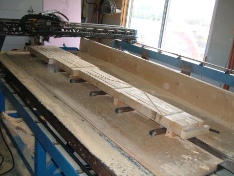
A few months after Ron joined our little band of windmill making friends we had three identical to a very small fraction of a millimeter absolutely flawless blades sitting on the bench with trailing edges so thin that you could read the newspaper through them. We sat around for a day just looking at them :) These were then given a coat of fibreglass and using an ingenious system that Ron came up with that would make them rot-proof for many years were mated to the rotor plate. For the first time all the components were ready.
The machine was painted a spiffy blue, the blades white, sliprings and an electrical connection box were added and we set off to place it on the tower that we’d installed over the summer.
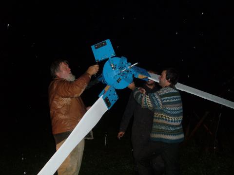
The final assembly took place in the rain, and by the time we were done it was too dark to even see the machine sitting on top of its 20 meter high (60’) tower so we took it back down and waited until the following morning. We also had to tweak the balance a hair once it started moving, you can get only so close with static balancing alone. For proper balance you have to observe the machine moving. The slightest error and it will show up as ever increasing oscillations and vibration in the mount. We ended up balancing the machine on the ground and there is not much else that is scarier up close than a windmill of this size running at a few hundred RPM. You really have to have good faith in your design and welding skills. I must have checked the mount 50 times before trying this. The rotor weighs in at a good 40 Kg and I’d hate to think what would happen if it struck something (or someone). There is a lot of energy in a system like that and the blade tips move at roughly 150 meters per second ((3.14 * 5 * 600) / 60) (550 Km/h or about 330 MPh) when it is going at its rull speed of 600 RPM! Nothing to sneeze at.
Running it for the first time and seeing it make power was - outside of my children being born - one of the high points of my life to date and even though from an economical point of view this project was an absolutely terrible loss the amount of satisfaction of seeing a dream like that come true is truly amazing. In the end the machine produced 2250 Watts at 10 m/s winds, so a hair under design power. Probably with some more tuning of the airgap we could have gotten spot on but 10% more did not seem worth re-doing a substantial portion of the work on the rotor drum. That would also mean running the coils close to their maximum temperature and it doesn’t hurt to have a bit of safety margin there.
Many thanks to:
Ron Brown
Tom Wilkinson
Dan Bartman
Matt Bartman
Wayne Abraham (+)
Mirka Jucha
Chris Stevens
Ed Arthurs
Johannes van den Dop
Laurence & Dina McKay
All the people at otherpower.com/fieldlines.com that helped with tips and tricks, especially ‘flux’, ‘kurt’, ‘donc’ and ‘marty’. Out of sight is not out of mind guys, you may be a continent away these days but you’re not forgotten.
(*) Edited after a comment on HN pointed out an error here. Thanks HN :)